
ELE-360 · Lesson 8 of 12 · 23 min
Reflection and transmission of waves
A wave that meets a change of material is partly reflected and partly transmitted. The TLR-1 signal reflects from the pavement, from building walls and from passing buses; it passes through the polycarbonate cap that protects the pole antenna and is blocked by the aluminum of the cabinet. Each of those interactions follows from the boundary conditions of lesson 6 applied to plane waves. This lesson starts with the simplest case, a plane wave striking a flat interface head-on, then adds layers such as a radome or a wall, then oblique incidence with its two polarizations, the Brewster angle and total internal reflection, and finishes with the electromagnetic shielding of enclosures, where reflection does most of the work and openings do most of the damage.
Normal incidence on a plane interface
Let a plane wave traveling in +z in medium 1 (impedance η₁) strike the plane z = 0, beyond which lies medium 2 (impedance η₂). Part of the wave reflects back into medium 1 and part continues into medium 2. The boundary conditions require tangential E and tangential H to be continuous at z = 0. Writing the incident, reflected and transmitted fields with the plane-wave rule H = ±E/η and imposing continuity gives the reflection coefficient Γ and transmission coefficient τ for the electric field. The same formula will reappear in lesson 9 for voltage waves on a transmission line meeting a load, with characteristic impedances in place of intrinsic impedances.
The fraction of incident power reflected is |Γ|² and, for lossless media, the fraction transmitted is 1 − |Γ|². Note that τ can exceed 1: going from a low-impedance to a high-impedance medium, the transmitted electric field is larger than the incident one, but the transmitted power is still less, because power density is E²/η and η₂ is larger. From air into a dielectric with ε_r, η₂ = η₀/√ε_r, so Γ = (1 − √ε_r)/(1 + √ε_r), which is negative: the reflected electric field is inverted. Polycarbonate (ε_r ≈ 2.9) reflects about 7 percent of the incident power, glass and concrete about 18 percent, wet soil about a third and seawater about 70 percent at 915 MHz.
A perfect conductor has η₂ = 0, so Γ = −1. The reflected wave has the same amplitude as the incident one and is inverted. The two traveling waves add to a standing wave, E = −2jE⁺ sin βz, whose nulls are fixed in space at the wall and every half wavelength from it, with maxima of twice the incident amplitude a quarter wavelength from the wall. The magnetic field has its maxima at the wall, where the surface current flows. A receiver moved along a line toward a metal wall sees its signal rise and fall every half wavelength, about 16 cm at 915 MHz. Leo saw exactly that while walking a test receiver toward the cabinet door during the ELE-350 field trial, and Amara now has the explanation.
Worked problem
Reflection from the pavement and from the cabinet
Find the reflection coefficient and the reflected power fraction for a 915 MHz wave at normal incidence on wet soil, modeled as ε_r = 15 with an effective conductivity of 0.05 S/m, and on the aluminum cabinet.
Show solution
- \[\eta_{\text{soil}} = \sqrt{\frac{j\omega\mu_0}{\sigma + j\omega\varepsilon}} \approx 97\ \Omega \ \text{(complex)}\]
- \[|\Gamma_{\text{soil}}| = \Big|\frac{\eta_{\text{soil}} - 376.7}{\eta_{\text{soil}} + 376.7}\Big| = 0.59 \qquad |\Gamma|^2 = 0.35\]
- \[\eta_{\text{Al}} \approx (1 + j)\sqrt{\frac{\pi f\mu_0}{\sigma}} = (1+j)\,0.010\ \Omega \qquad |\Gamma_{\text{Al}}| \approx 1.000\]
Answer: Wet ground reflects about 35 percent of the power at normal incidence, and, as the oblique-incidence results below show, much more at the grazing angles typical of a link across an intersection. The cabinet reflects essentially everything; the aluminum's impedance is a hundredth of an ohm against free space's 377.
Layers: radomes, windows and walls
A slab of material between two regions of air reflects from both faces, and the two reflections interfere. If the slab is a half wavelength thick in the material, the round trip inside it is a full wavelength plus the sign change at one face, and the two reflections cancel: a half-wave slab is transparent at its design frequency. A slab a quarter wavelength thick has reflections that add, the worst case. A slab much thinner than a wavelength is nearly transparent because the two reflections, of opposite sign, almost cancel. The general case is handled by a transfer matrix that chains the slab's propagation and impedance, exactly the ABCD matrix of a transmission-line section that lesson 10 uses, so the same code serves both.
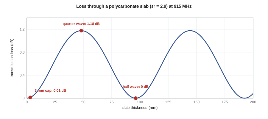
The pole antenna of the TLR-1 sits under a polycarbonate cap 3 mm thick. The wavelength in polycarbonate at 915 MHz is about 19 cm, so 3 mm is thin and the cap costs about 0.01 dB. A cap 48 mm thick, a quarter wavelength, would reflect nearly a quarter of the power and cost about 1.2 dB; one 96 mm thick, a half wavelength, would be transparent again. For radomes at microwave frequencies, where the wavelength is a few centimeters, designers choose thin walls, half-wave walls or sandwich constructions for exactly these reasons. Window glass 6 mm thick costs a few tenths of a decibel. A plain concrete wall 200 mm thick, in this simple model, costs about 5 dB, mostly from absorption; measured losses through real walls are often larger because of reinforcing steel, moisture and layered construction, and metallized low-emissivity glass can block a window almost completely.
Oblique incidence
When a wave strikes an interface at an angle θᵢ from the normal, the reflected wave leaves at the same angle, and the transmitted wave bends according to Snell's law, n₁ sin θᵢ = n₂ sin θₜ, where n = √(μ_rε_r) is the refractive index. The reflection coefficients now depend on polarization. A wave whose E is perpendicular to the plane of incidence (the plane containing the incident direction and the surface normal) is called TE or perpendicular polarization. One whose E lies in the plane of incidence is TM or parallel polarization. For a TLR-1 link with vertical antennas over horizontal ground, the plane of incidence is vertical and the vertically polarized signal is TM; a horizontally polarized system would be TE.
For TE polarization, the reflection grows steadily from its normal-incidence value toward 1 at grazing incidence. For TM polarization, the reflection first falls, reaching zero for a lossless second medium at the Brewster angle θ_B = arctan √(ε_r2/ε_r1), then rises to 1 at grazing incidence. For wet ground with ε_r ≈ 15, the Brewster angle is about 75° from the normal, that is, about 15° above the horizon. Light reflected from water or a road is strongly TE-polarized for the same reason, which is how polarized sunglasses cut glare. Real ground has loss, so the TM minimum is small but not zero, and the angle is called the pseudo-Brewster angle.
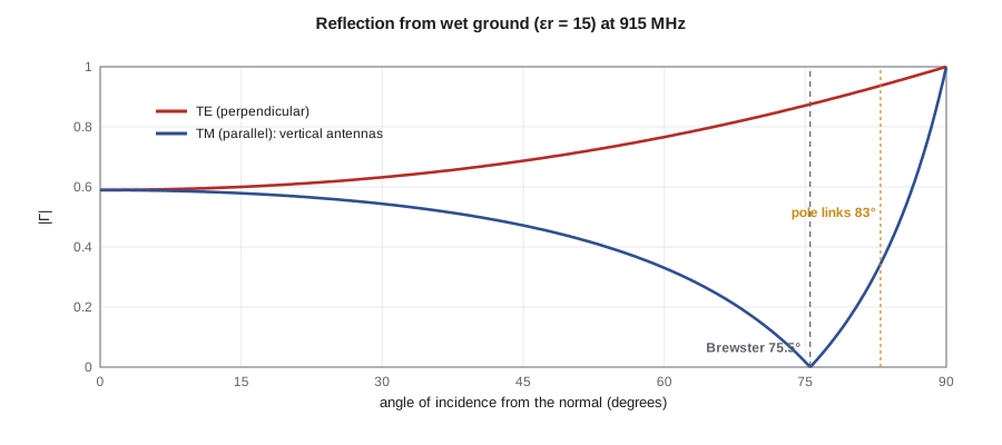
For a link across an intersection, the ground reflection arrives at a shallow angle. With antennas at 3 m and 2.5 m and a path of 45 m, the reflected ray strikes the ground about 7° above the horizon, 83° from the normal. There the TE coefficient is about 0.94 but the TM coefficient only about 0.34, so for the vertically polarized pole links the ground reflection is fairly weak, one reason those links behaved so well in the ELE-350 field trial. On the 600 m cabinet-to-cabinet link with antennas at 6 m, the angle is only about 1.1°, the TM coefficient rises to about 0.85, and the ground-reflected ray, nearly equal in strength and inverted, partly cancels the direct ray. That is the physical basis of the two-ray model and its breakpoint distance in ELE-350 lesson 11, beyond which the received power falls as 1/d⁴ instead of 1/d².
Total internal reflection
Going from a denser medium into a less dense one, n₁ > n₂, Snell's law gives sin θₜ > 1 for incidence beyond the critical angle θ_c = arcsin(n₂/n₁). No real transmitted angle exists; the wave is totally reflected, and the field beyond the boundary decays exponentially as an evanescent wave carrying no average power. Optical fibers guide light by total internal reflection at the boundary between core and cladding. In printed-circuit boards a mild version occurs at the interface between FR-4 and air, which partly traps fields in the board and contributes to the effective permittivity of lesson 11. Evanescent fields also appear in waveguides below cut-off and in the near field of antennas.
import math, cmath
eps0, mu0, c = 8.854e-12, 4e-7 * math.pi, 2.998e8
f = 915e6; w = 2 * math.pi * f; eta0 = math.sqrt(mu0 / eps0)
def medium(er, sig):
    """Complex intrinsic impedance and propagation constant at 915 MHz."""
    ec = er * eps0 - 1j * sig / w
    return cmath.sqrt(mu0 / ec), 1j * w * cmath.sqrt(mu0 * ec)
# 1. Normal incidence from air
print("material          |Gamma|   reflected power")
for name, er, sig in (("polycarbonate", 2.9, 0), ("glass", 6, 0), ("typical concrete", 6, 0.03),
                      ("wet soil", 15, 0.05), ("seawater", 81, 4.0), ("aluminum", 1, 3.5e7)):
    eta2, _ = medium(er, sig)
    G = (eta2 - eta0) / (eta2 + eta0)
    print(f"{name:16s} {abs(G):7.3f}   {abs(G)**2 * 100:8.1f} %")
# 2. A slab in air: ABCD (transfer) matrix at normal incidence
def slab(er, sig, d):
    eta, gam = medium(er, sig)
    A, B = cmath.cosh(gam * d), eta * cmath.sinh(gam * d)
    C, D = cmath.sinh(gam * d) / eta, cmath.cosh(gam * d)
    den = A + B / eta0 + C * eta0 + D
    return abs(2 / den) ** 2, abs((A + B / eta0 - C * eta0 - D) / den) ** 2
lq = c / f / math.sqrt(2.9) / 4                      # quarter wavelength in polycarbonate
for name, er, sig, d in (("polycarbonate cap 3 mm", 2.9, 0, 0.003), (f"polycarbonate {lq*1e3:.0f} mm (quarter wave)", 2.9, 0, lq),
                         (f"polycarbonate {2*lq*1e3:.0f} mm (half wave)", 2.9, 0, 2 * lq), ("window glass 6 mm", 6, 0, 0.006),
                         ("concrete wall 200 mm", 6, 0.03, 0.2)):
    T, R = slab(er, sig, d)
    print(f"{name:37s} loss {-10 * math.log10(T):5.2f} dB, reflected {R * 100:5.1f} %")
# 3. Oblique incidence on wet ground (lossless model): Fresnel coefficients
er2 = 15.0
print("angle from normal   |Gamma_TE|  |Gamma_TM|")
for th in (0, 30, 60, 75, 80, 83, 89):
    ci, si = math.cos(math.radians(th)), math.sin(math.radians(th))
    root = cmath.sqrt(er2 - si * si)
    GTE = (ci - root) / (ci + root)
    GTM = (er2 * ci - root) / (er2 * ci + root)
    print(f"{th:10d}          {abs(GTE):8.3f}   {abs(GTM):8.3f}")
print(f"Brewster angle: {math.degrees(math.atan(math.sqrt(er2))):.1f} deg from the normal")
# 4. Rule-of-thumb shielding of a single slot of length l (valid for l below lambda/2)
lam = c / f
for l in (0.10, 0.05, 0.02):
print(f"slot {l * 1e3:4.0f} mm long: shielding about {20 * math.log10(lam / (2 * l)):5.1f} dB")material |Gamma| reflected power
polycarbonate 0.260 6.8 %
glass 0.420 17.7 %
typical concrete 0.422 17.8 %
wet soil 0.590 34.8 %
seawater 0.840 70.5 %
aluminum 1.000 100.0 %
polycarbonate cap 3 mm loss 0.01 dB, reflected 0.3 %
polycarbonate 48 mm (quarter wave) loss 1.18 dB, reflected 23.7 %
polycarbonate 96 mm (half wave) loss 0.00 dB, reflected 0.0 %
window glass 6 mm loss 0.34 dB, reflected 7.5 %
concrete wall 200 mm loss 5.06 dB, reflected 7.5 %
angle from normal |Gamma_TE| |Gamma_TM|
0 0.590 0.590
30 0.632 0.544
60 0.766 0.330
75 0.871 0.017
80 0.911 0.180
83 0.937 0.344
89 0.991 0.869
Brewster angle: 75.5 deg from the normal
slot 100 mm long: shielding about 4.3 dB
slot 50 mm long: shielding about 10.3 dB
slot 20 mm long: shielding about 18.3 dBThe tables reproduce the numbers in the text. The slab results show the thin cap, the quarter-wave worst case and the half-wave transparency, and the plain-concrete wall. The Fresnel table shows the TM coefficient falling almost to zero near 75° and both coefficients approaching 1 near grazing; at 83°, the angle of the pole links, TE is about 0.94 and TM about 0.34, and by 89° both exceed 0.85, so on the long cabinet link the ground reflection is strong for either polarization. The slot results are the subject of the last section.
Shielding effectiveness
Shielding effectiveness is the ratio, in decibels, of the field at a point without a shield to the field with it. For a solid conducting wall, it is the sum of three terms. Reflection loss comes from the huge impedance mismatch between the wave and the metal, tens of decibels at radio frequencies. Absorption loss is 8.7 dB per skin depth of thickness, which lesson 7 showed is thousands of decibels for any practical sheet at 915 MHz. A small correction accounts for re-reflections inside thin sheets. For a closed metal box, the theoretical shielding is therefore enormous, far beyond what can be measured.
Real enclosures have seams, ventilation holes, connector openings, displays and doors. Each opening leaks. A useful rule of thumb treats a single slot of length l, below half a wavelength, as providing about 20 log(λ/(2l)) dB of shielding. At 915 MHz, where λ/2 is 16 cm, a 100 mm seam between a lid and its box gives only about 4 dB, a 50 mm gap about 10 dB and a 20 mm slot about 18 dB. A slot near half a wavelength long can resonate and radiate as efficiently as an antenna, a slot antenna. The shielding of a real box is thus set by its longest opening, not its area, which is why gaskets and closely spaced screws matter more than the thickness of the metal. Multiple small holes are much better than one long slot of the same area.
Amara uses these rules for both products. The TLR-1 enclosure's lid needs screws or a conductive gasket at intervals of no more than about λ/20, around 16 mm at 915 MHz, if the enclosure is to keep the radio's harmonics inside and the cabinet's other emissions out; with the 2.4 GHz and 5 GHz radios that share many cabinets, closer spacing helps. The APS-2's speaker grille is a pattern of small holes rather than slots, and the button-cap opening is ringed by the bonding spring of lesson 3, which also closes the slot around the cap. Lesson 12 returns to shielding when the antenna has to be outside the box while everything else stays in.
Common mistakes
MistakeAssuming τ = 1 + Γ means transmitted power can exceed incident power.
InsteadPower density is E²/η; the transmitted power fraction is 1 − |Γ|² for lossless media.
MistakeUsing the TE coefficient for a vertical antenna over ground.
InsteadWith a vertical plane of incidence, vertical polarization is TM; it has a Brewster minimum.
MistakeMaking a radome a quarter wavelength thick.
InsteadQuarter-wave walls reflect the most; use thin or half-wave walls.
MistakeJudging enclosure shielding by sheet thickness.
InsteadThe longest seam or slot sets the shielding; close it with gaskets or closely spaced fasteners.
Summary and key terms
- At normal incidence, Γ = (η₂ − η₁)/(η₂ + η₁) and τ = 1 + Γ; a perfect conductor gives Γ = −1 and a standing wave.
- Slabs reflect from both faces; thin and half-wave slabs are nearly transparent, quarter-wave slabs reflect most.
- At oblique incidence, Snell's law sets the transmitted angle and reflection depends on TE or TM polarization.
- TM reflection vanishes at the Brewster angle for lossless media; near grazing both polarizations reflect almost fully.
- Beyond the critical angle, waves are totally internally reflected and the field beyond is evanescent.
- Solid metal shields very well; openings limit real enclosures, with a slot of length l giving about 20 log(λ/2l) dB.
- Reflection coefficient
- Γ, the ratio of reflected to incident field at an interface.
- Standing wave
- The sum of equal forward and reflected waves, with fixed nulls and maxima.
- Snell's law
- n₁ sin θᵢ = n₂ sin θₜ, relating angles of incidence and transmission.
- TE polarization
- E perpendicular to the plane of incidence; also called perpendicular polarization.
- TM polarization
- E in the plane of incidence; also called parallel polarization.
- Brewster angle
- The angle at which TM reflection from a lossless dielectric vanishes.
- Total internal reflection
- Complete reflection at an interface into a less dense medium beyond the critical angle.
- Shielding effectiveness
- The reduction, in decibels, of a field by a shield.
Practice problems
Work each problem on paper first, then reveal the answer to check.
Find Γ and the reflected power fraction at normal incidence from air onto a dielectric with ε_r = 9.
Show answer
η₂ = 125.6 Ω, Γ = −0.5, 25 %.
How far from a metal wall is the first electric-field null of a 915 MHz standing wave, and the first maximum?
Show answer
At the wall, then every 16.4 cm; the first maximum is 8.2 cm from the wall.
What thickness makes a half-wave radome of ε_r = 4 at 2.45 GHz?
Show answer
λ_d/2 = 12.24/(2 × 2) = 3.06 cm.
Find the Brewster angle for glass of ε_r = 6.
Show answer
arctan √6 = 67.8° from the normal.
Find the critical angle from FR-4 (ε_r = 4.4) to air.
Show answer
arcsin(1/√4.4) = 28.5°.
Estimate the shielding of a 30 mm slot at 2.4 GHz.
Show answer
λ = 125 mm; 20 log(125/60) = 6.4 dB.
Lesson quiz · 5 questions
Score 60% or more to complete this lesson.
Create a free account to save your progress, take quizzes and earn a certificate.