
ELE-350 · Lesson 6 of 12 · 23 min
Baseband pulse transmission and intersymbol interference
Once a message is a stream of bits, it has to be turned back into a waveform to travel. The simplest way is to send one pulse per bit, positive for a one and negative for a zero. The shape of those pulses decides how much bandwidth the signal needs, how well the receiver can recover the timing, and whether neighboring pulses blur into one another. This lesson covers line codes, the bandwidth of pulse trains, intersymbol interference and the Nyquist criterion that eliminates it, raised-cosine pulse shaping, multilevel signaling, eye diagrams and equalization. Everything here applies directly at baseband, on a cable or inside a chip, and it also applies to radio signals, because a digital modulator is a baseband pulse stream shifted to a carrier.
Amara has to set the TLR-1's data rate. Higher rates make each message shorter, which reduces the chance that a burst of interference hits it and frees air time for the listen-in clips of lesson 5. Lower rates need less bandwidth and, as lesson 7 will show, collect less noise, so they reach farther. The pulse shape links rate to bandwidth, and the regulations of lesson 12 put a limit on bandwidth and power density. She starts with the baseband question: how much bandwidth does a given bit rate need?
Line codes
A line code assigns a waveform to each bit. Unipolar non-return-to-zero (NRZ) sends +V for a one and 0 for a zero for the full bit time T_b. Polar NRZ sends +V and −V, which gives the same noise margin with half the average power and no DC component on average. Return-to-zero (RZ) codes use pulses only half a bit long, which doubles the bandwidth but guarantees transitions for timing recovery. Bipolar, or alternate mark inversion (AMI), sends zeros as 0 and alternates the polarity of successive ones, so there is no DC and a single error is detectable because it breaks the alternation; it was the T1 line code. Manchester code sends each bit as a transition in the middle of the bit, high-to-low for one value and low-to-high for the other, so every bit carries a clock edge and there is never any DC, at the cost of twice the bandwidth; early Ethernet used it.
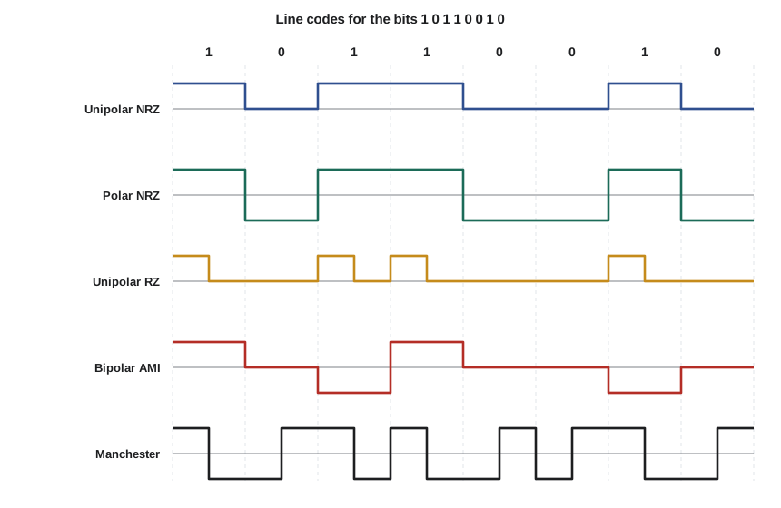
Choosing a line code means balancing three needs. The receiver must recover the bit clock from the signal itself, so long runs without transitions are dangerous. Many channels, such as transformer-coupled lines and AC-coupled amplifiers, cannot pass DC, so the code should have little low-frequency content. And bandwidth is limited, so the code should be compact. Radio systems usually solve the first two needs differently, by scrambling or whitening the data with a pseudo-random sequence so that long runs of identical bits become very unlikely, and then using compact polar pulses.
Bandwidth of a pulse train
For random, equally likely bits, the power spectral density of a polar NRZ signal has the shape of the pulse's spectrum squared: S(f) = V²T_b sinc²(fT_b). Its first null is at f = R_b = 1/T_b, and as lesson 1 showed, the main lobe holds about 90 percent of the power. Rectangular pulses therefore need a baseband bandwidth of about R_b to pass most of their power, with slowly decaying sidelobes beyond. The question is whether a narrower band is possible, and what happens to the pulses if the channel cuts the band short.
Intersymbol interference
A band-limited channel spreads each pulse in time. A rectangular pulse passed through a low-pass filter comes out rounded, with a tail that extends into the next bit periods. At the sampling instant of a later bit, the sum of tails from earlier bits adds to or subtracts from that bit's own value. This is intersymbol interference (ISI), and it is different from noise: it is caused by the signal itself, it gets worse with higher rates rather than weaker signals, and turning up the transmitter power does not cure it. If the ISI is large enough, a bit can be read wrongly even with no noise at all.
The total received sample at instant k is the wanted symbol scaled by the pulse's peak, plus the contributions of all other symbols at their offsets. If p(t) is the received pulse shape and a_k are the symbol values, the sample is
The middle term is the ISI. It vanishes if the pulse is zero at every nonzero multiple of the symbol period. Pulses need not be short to achieve this; they only need to cross zero at the right instants.
The Nyquist criterion
Nyquist showed in the 1920s that a pulse with p(0) = 1 and p(kT) = 0 for every other integer k produces zero ISI, and that this is possible only if the shifted copies of its spectrum, repeated every 1/T, add up to a constant. The narrowest spectrum that meets the condition is a rectangle from −1/(2T) to +1/(2T), whose pulse is the sinc function. The symbol rate R_s = 1/T can therefore be sent without ISI in a baseband bandwidth of R_s/2, the Nyquist bandwidth, and no less. At radio frequency, after modulation onto a carrier, the band is twice as wide, R_s.
The ideal sinc pulse cannot be used in practice. Its spectrum has perfectly sharp edges, which no filter can make, and its tails decay only as 1/t, so a small timing error makes the tails of many symbols add up, possibly to a large ISI. Practical systems give up a little bandwidth to get pulses whose tails decay much faster.
Raised-cosine pulses
The raised-cosine family satisfies the Nyquist criterion with a spectrum whose edges roll off gradually as half a cosine cycle. The roll-off factor α, between 0 and 1, sets the excess bandwidth: α = 0 is the sinc pulse, α = 1 doubles the Nyquist bandwidth, and values from 0.2 to 0.5 are common. The pulse still crosses zero at every multiple of T, and its tails decay as 1/t³, so timing errors do far less harm.
In a real system the filtering is split equally between transmitter and receiver. Each uses a root-raised-cosine filter whose response is the square root of the raised-cosine spectrum, so the cascade has the raised-cosine response and zero ISI, and the receiver's filter is also matched to the transmitted pulse, which lesson 9 will show is optimal for noise. Many low-cost radios instead use a Gaussian filter, which does not satisfy the Nyquist criterion exactly but has a compact spectrum and no ringing; the bandwidth-time product BT sets how much ISI it adds, and GFSK with BT = 0.5 is common in sub-gigahertz and Bluetooth radios.
import math
def rc(t, a):                       # raised-cosine pulse, t in symbol periods
    if abs(t) < 1e-12: return 1.0
    if a > 0 and abs(abs(t) - 1 / (2 * a)) < 1e-9:
        return (math.pi / 4) * math.sin(math.pi / (2 * a)) / (math.pi / (2 * a))
    return math.sin(math.pi * t) / (math.pi * t) * math.cos(math.pi * a * t) / (1 - (2 * a * t) ** 2)
for a in (0.0, 0.35, 1.0):
    row = []
    for tau in (0.0, 0.1, 0.2):     # sampling-time error, fraction of a symbol
        isi = sum(abs(rc(k + tau, a)) for k in range(-40, 41) if k != 0)
        row.append(f"tau = {tau:.1f}: eye = {rc(tau, a) - isi:+.3f}")
    print(f"alpha = {a:.2f}  " + "   ".join(row))
Rb = 50e3
for a in (0.0, 0.25, 0.5, 1.0):
print(f"50 kb/s binary, alpha = {a:.2f}: baseband {Rb*(1+a)/2/1e3:5.1f} kHz, RF {Rb*(1+a)/1e3:5.1f} kHz")alpha = 0.00 tau = 0.0: eye = +1.000 tau = 0.1: eye = +0.140 tau = 0.2: eye = -0.684 alpha = 0.35 tau = 0.0: eye = +1.000 tau = 0.1: eye = +0.717 tau = 0.2: eye = +0.411 alpha = 1.00 tau = 0.0: eye = +1.000 tau = 0.1: eye = +0.896 tau = 0.2: eye = +0.736 50 kb/s binary, alpha = 0.00: baseband 25.0 kHz, RF 50.0 kHz 50 kb/s binary, alpha = 0.25: baseband 31.2 kHz, RF 62.5 kHz 50 kb/s binary, alpha = 0.50: baseband 37.5 kHz, RF 75.0 kHz 50 kb/s binary, alpha = 1.00: baseband 50.0 kHz, RF 100.0 kHz
The output makes the trade clear. With perfect timing every raised-cosine pulse gives a full eye opening of 1.000, because the ISI is exactly zero. With a timing error of one tenth of a symbol, the sinc pulse's slowly decaying tails add up to shrink the worst-case eye to about a seventh of its height, while α = 0.35 keeps about 72 percent of it and α = 1 about 90 percent. At a fifth of a symbol, the sinc eye is closed outright. The bandwidth cost of α = 0.35 is only 35 percent above the Nyquist minimum.
The eye diagram
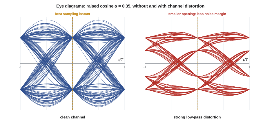
An eye diagram is made by overlaying many symbol periods of the received waveform on an oscilloscope triggered by the symbol clock. With random data, every possible pattern of neighboring symbols appears, and the traces form an eye-shaped opening. The height of the opening at the sampling instant is the noise margin: how much noise can be added before a decision goes wrong. The width of the opening is the timing margin. The slope of the sides shows how sensitive the system is to timing error, and the thickness of the trace bundle at the zero crossings is the timing jitter. ISI narrows the eye vertically, noise blurs it, and a closed eye means errors even before noise is considered.
Multilevel signaling
Sending more than two levels carries more than one bit per symbol. M-ary pulse-amplitude modulation uses M levels, so each symbol carries log₂M bits, and the symbol rate for a given bit rate is lower: four levels carry 2 bits per symbol, halving the bandwidth. The cost is noise margin. With the peak amplitude fixed, the levels are closer together, so less noise causes an error; for the same error rate, 4-level PAM needs about 7 dB more SNR than binary, and every doubling of M beyond that costs about 6 dB more. Lesson 8 applies the same trade to carrier modulation, where it leads to 16-QAM and beyond.
Equalization and timing recovery
When a channel's response is not flat, as in a long cable, a telephone line or a radio path with echoes, the received pulses no longer meet the Nyquist criterion and the eye closes. An equalizer is a filter at the receiver that undoes the channel's distortion. The simplest is a tapped delay line, an FIR filter with taps spaced one symbol apart. A zero-forcing equalizer chooses the taps to force the combined response to zero at the neighboring sampling instants, which removes ISI but can amplify noise where the channel response is weak. A minimum mean-square-error equalizer balances the two. Adaptive equalizers update their taps continuously, usually with the least-mean-squares algorithm, using a known training sequence and then their own decisions. Every telephone-line modem, cable modem and cellular receiver has one.
The receiver also has to sample at the right instants. A timing recovery loop adjusts the sampling clock to keep samples at the center of the eye, using the zero crossings of the received signal or an error measure computed from the samples. A packet radio like the TLR-1 begins every packet with a preamble, an alternating 1010 pattern that gives the timing loop and the AGC something to lock onto, followed by a sync word that marks where the data begins. A longer preamble makes acquisition more reliable but adds air time to every packet.
Worked problem
Data rate and bandwidth for the TLR-1
The TLR-1 will send packets of 32 bytes: 4 bytes of preamble, 4 bytes of sync word and header, 22 bytes of payload and a 2-byte check. Compare air times and RF bandwidths at 10 kb/s and 50 kb/s with binary signaling and raised-cosine filtering with α = 0.35.
Show solution
- \[\text{bits per packet} = 32 \times 8 = 256\]
- \[10\ \text{kb/s: } t = 25.6\ \text{ms}, \quad B_{RF} = 1.35 \times 10 = 13.5\ \text{kHz}\]
- \[50\ \text{kb/s: } t = 5.12\ \text{ms}, \quad B_{RF} = 1.35 \times 50 = 67.5\ \text{kHz}\]
Answer: At 10 kb/s a packet takes a quarter of the 100 ms latency budget before any retry; at 50 kb/s it takes 5 ms, leaving room for several retries and for the listen-in clips. The fivefold wider band at 50 kb/s collects five times the noise, a 7 dB sensitivity penalty, which lessons 7 and 11 will weigh against the range needed. Amara pencils in 50 kb/s.
Common mistakes
MistakeTreating ISI as if it were noise that more power can overcome.
InsteadISI scales with the signal; reduce it with pulse shaping and equalization.
MistakeUsing sinc pulses because they need the least bandwidth.
InsteadTheir slowly decaying tails make the system very sensitive to timing error; use a raised cosine with α of 0.2 to 0.5.
MistakeQuoting baseband bandwidth for a modulated signal.
InsteadAfter modulation onto a carrier, the RF bandwidth is twice the baseband bandwidth: (1 + α)R_s.
MistakePutting the whole raised-cosine filter at the transmitter.
InsteadSplit it as root-raised-cosine filters at both ends so the receiver filter is matched to the pulse.
Summary and key terms
- Line codes trade bandwidth against DC content and timing information; radios usually scramble data and send polar pulses.
- Band-limited channels spread pulses in time, and the tails of neighboring pulses cause intersymbol interference.
- Zero ISI requires pulses that cross zero at every nonzero multiple of T; the minimum baseband bandwidth is R_s/2.
- Raised-cosine pulses use (1 + α)R_s/2 of baseband bandwidth and tolerate timing errors far better than sinc pulses.
- The eye diagram shows noise margin, timing margin and jitter at a glance.
- M-level signaling divides the symbol rate by log₂M at a cost in noise margin; equalizers and timing loops keep the eye open.
- Line code
- The rule that assigns a waveform to each bit or group of bits.
- Intersymbol interference
- Distortion of a symbol's sample by the tails of neighboring symbols.
- Nyquist bandwidth
- The minimum baseband bandwidth, half the symbol rate, for transmission without ISI.
- Roll-off factor
- The fraction of excess bandwidth beyond the Nyquist bandwidth in a raised-cosine spectrum.
- Root-raised-cosine filter
- A filter whose response is the square root of a raised-cosine spectrum, used at both transmitter and receiver.
- Eye diagram
- An overlay of many symbol periods of a received signal showing noise and timing margins.
- Equalizer
- A receiver filter that compensates for the channel's frequency response.
- Preamble
- A known pattern at the start of a packet used for gain control and synchronization.
Practice problems
Work each problem on paper first, then reveal the answer to check.
Find the minimum baseband bandwidth for 2400 symbols per second without ISI.
Show answer
1200 Hz.
A link sends 9600 b/s with 4-level PAM and α = 0.5. Find the symbol rate and baseband bandwidth.
Show answer
4800 symbols/s; (1.5)(4800)/2 = 3600 Hz.
Which line code would you choose for a transformer-coupled link that needs a clock edge in every bit?
Show answer
Manchester code: no DC and a transition in every bit.
What does the height of the eye opening represent?
Show answer
The noise margin at the sampling instant.
A 256-bit packet at 100 kb/s with α = 0.25: find air time and RF bandwidth.
Show answer
2.56 ms; 125 kHz.
Why does an AMI code allow detection of single errors?
Show answer
Ones must alternate in polarity; a single error breaks the alternation, a bipolar violation.
Lesson quiz · 5 questions
Score 60% or more to complete this lesson.
Create a free account to save your progress, take quizzes and earn a certificate.