
ELE-350 · Lesson 4 of 12 · 28 min
Superheterodyne receivers and mixers
A radio receiver has to pick one weak signal out of a crowd of strong ones, amplify it by a factor of a million or more without oscillating, and hand a clean signal to the demodulator. Doing all that at the signal's own frequency is hard: filters sharp enough to separate neighboring channels at 915 MHz are difficult to make, and they cannot be tuned. The superheterodyne receiver, invented about a century ago, solves the problem by shifting every incoming signal to one fixed intermediate frequency where amplification and filtering are easy. Nearly every radio built since, from broadcast receivers to cellular handsets, uses the idea or one of its modern descendants. This lesson explains the mixer, the superheterodyne architecture, the image problem, spurious responses and intermodulation, and the direct-conversion and low-IF receivers used in integrated transceivers like the one in the TLR-1.
The design question is concrete. During a service visit, a traffic technician parks a truck with a 5 W land-mobile radio beside the cabinet and talks to the dispatcher while the cabinet's TLR-1 is trying to hear a pole station 45 m away. The wanted signal may be −95 dBm; the truck radio's signal at the cabinet antenna may be stronger than −10 dBm, more than eighty-five decibels stronger. Amara needs to know what a receiver does with signals like that, and what to ask of the transceiver chip she selects.
What a receiver must do
Three properties describe a receiver. Sensitivity is the weakest signal it can demodulate to a stated quality, set by its noise, which lesson 7 quantifies. Selectivity is its ability to reject signals on other frequencies, set by its filters. Dynamic range is the span between the weakest signal it can receive and the strongest it can tolerate without distortion, set by the linearity of its amplifiers and mixers. A good design needs all three at once, and they conflict: gain helps sensitivity but strong signals then overload later stages; sharp filters help selectivity but add loss before the first amplifier.
The earliest receivers, called tuned radio frequency (TRF) receivers, used several tuned amplifier stages at the signal frequency. Every stage had to be tuned together as the listener changed stations, the bandwidth of a tuned circuit of fixed Q grows with frequency so selectivity varied across the band, and high gain at one frequency invited oscillation through stray feedback. The superheterodyne principle removed all three problems.
The mixer
A mixer multiplies the incoming signal by a local oscillator (LO). By the identity cos a cos b = ½[cos(a − b) + cos(a + b)], the product of signals at f_RF and f_LO contains the difference and sum frequencies. If the LO is tuned so that the difference equals a fixed intermediate frequency f_IF, any modulation on the RF signal is transferred unchanged to the IF signal. A filter at f_IF keeps the difference and rejects the sum.
With high-side injection, f_LO = f_RF + f_IF, the spectrum is reversed at IF, which matters for SSB and for the sign of FSK tones but not for AM or a symmetric signal. With low-side injection, f_LO = f_RF − f_IF, the spectrum keeps its orientation. Practical mixers are not ideal multipliers. A diode ring mixer switches the RF signal's polarity at the LO rate and is passive, so it has a conversion loss of about 6 dB or more. A Gilbert cell, a pair of differential pairs from ELE-340 driven by the LO and fed by a transconductance stage carrying the RF signal, gives conversion gain and is the standard in integrated receivers. Both behave like multiplication by a square wave, so they also produce responses at odd harmonics of the LO.
The superheterodyne architecture
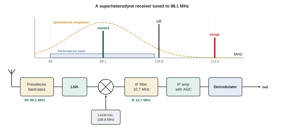
In the superheterodyne receiver the antenna signal passes through a preselector filter and a low-noise amplifier (LNA), then into the mixer. Tuning is done by changing only the LO frequency. All the hard work, the channel filtering and most of the gain, happens in the IF stages at a fixed frequency, where a ceramic, crystal or surface acoustic wave filter can have exactly the right shape. An automatic gain control (AGC) loop measures the IF signal level and adjusts the gain so that strong and weak stations produce the same level at the demodulator. Broadcast receivers have long used standard IFs: 455 kHz for medium-wave AM and 10.7 MHz for FM broadcast, which is why ceramic filters at those frequencies are cheap.
The image frequency
The mixer cannot tell whether the RF signal is below or above the LO. A signal at f_LO + f_IF produces the same difference frequency as the wanted signal at f_LO − f_IF. That second input is the image, and it lies 2f_IF away from the wanted frequency on the far side of the LO. Once the image reaches the mixer, nothing after it can remove the interference, because it is already on the IF. Only the preselector, before the mixer, can reject it.
Choosing the IF is a compromise. A high IF puts the image far away, so a broad, simple preselector can reject it. A low IF makes sharp, narrow channel filters easier and cheaper. For FM broadcast the choice of 10.7 MHz is clever: the image is 21.4 MHz above the wanted station, and the broadcast band is only 20 MHz wide, so every image falls outside the band where no strong broadcast station can be. For medium-wave AM with a 455 kHz IF, the image of a station at 600 kHz is at 1510 kHz, inside the band, so the preselector must be a tuned circuit that tracks the LO.
Worked problem
Images for three receivers
Find the LO and image frequencies, with high-side injection, for an FM receiver tuned to 98.1 MHz with a 10.7 MHz IF, an AM receiver tuned to 600 kHz with a 455 kHz IF, and a 915 MHz receiver with a 10.7 MHz IF.
Show solution
- \[\text{FM: } f_{LO} = 108.8\ \text{MHz}, \quad f_{image} = 98.1 + 21.4 = 119.5\ \text{MHz (above the band)}\]
- \[\text{AM: } f_{LO} = 1055\ \text{kHz}, \quad f_{image} = 600 + 910 = 1510\ \text{kHz (inside the band)}\]
- \[915\ \text{MHz: } f_{LO} = 925.7\ \text{MHz}, \quad f_{image} = 936.4\ \text{MHz}\]
Answer: The FM image is harmless because no broadcast station can be there. The AM image needs a tracking preselector. The 915 MHz image falls just above the band in a range used by licensed services, so a 10.7 MHz IF at 915 MHz would need a sharp RF filter; a higher first IF or an image-reject architecture is a better choice.
Two refinements are common. A double-conversion receiver uses a high first IF for image rejection and a low second IF for channel selection. An image-reject mixer, of the Hartley or Weaver type, uses two mixers driven by LO signals in quadrature, followed by a 90° shift and a sum, so the wanted signal adds and the image cancels. It is the receiving counterpart of the phasing SSB modulator of lesson 2, and it typically achieves 30 to 40 dB of image rejection limited by gain and phase matching.
Spurious responses
Because practical mixers are nonlinear and switch rather than multiply, they produce outputs at every combination m f_LO ± n f_RF. Any input frequency for which some combination falls on the IF is a spurious response. The image is the m = n = 1 case; others include the half-IF response, an input halfway between the wanted signal and the LO, which reaches the IF through the second harmonics of both. A strong signal at one of these frequencies is heard in the receiver as if it were on the channel. The design remedy is a frequency plan that keeps low-order spurs away from strong signals, plus enough preselection.
Intermodulation and blocking
Amplifiers and mixers are not perfectly linear either. Writing the output as a power series, y = a₁x + a₂x² + a₃x³, and driving it with two tones at f₁ and f₂ produces third-order products at 2f₁ − f₂ and 2f₂ − f₁. These lie close to the tones themselves, inside the receiver's passband, where no filter can remove them. Two strong signals at 916 and 917 MHz, for example, produce a product at 915 MHz, exactly where the TLR-1 is listening.
The third-order products grow three times as fast as the tones, 3 dB for every 1 dB increase, so on a log plot their line has slope 3 and the wanted output line has slope 1. The input level at which the two lines would cross, extrapolated from small signals, is the input third-order intercept point, IIP3. It is a figure of merit for linearity, and it gives the level of the product for any input power. A second figure, the 1 dB compression point, is the input power at which the gain has fallen by 1 dB; for a simple cubic nonlinearity it lies about 9.6 dB below IIP3.
A strong signal can harm reception even if it produces no product on the channel. It can drive the LNA or mixer into compression, reducing the gain for the wanted signal, which is called blocking or desensitization. It can also mix with noise sidebands of the LO, a problem called reciprocal mixing: a strong signal 1 MHz away, mixed with the LO's phase noise 1 MHz from the LO, lands noise directly on the IF. A receiver specification therefore lists a blocking level, the strongest signal at a stated offset that degrades sensitivity by no more than 3 dB.
Worked problem
Intermodulation from two strong signals
The TLR-1 receiver has IIP3 = −12 dBm. Two signals at 916 and 917 MHz each arrive at −45 dBm. Find the level of the 915 MHz product and compare it with a −105 dBm sensitivity.
Show solution
- \[2f_1 - f_2 = 2(916) - 917 = 915\ \text{MHz}\]
- \[P_{IM3} = 3(-45) - 2(-12) = -135 + 24 = -111\ \text{dBm}\]
Answer: The product is at −111 dBm, only 6 dB below the sensitivity level, so it would noticeably degrade a weak link. Raising both interferers by 5 dB would raise the product by 15 dB to −96 dBm, above the wanted signal. Filtering out-of-band signals before the LNA, and choosing a receiver with a higher IIP3, are the remedies.
import math
def image(f_rf, f_if, high_side=True):
    lo = f_rf + f_if if high_side else f_rf - f_if
    return lo, (lo + f_if if high_side else lo - f_if)
for name, f, fif in (('FM', 98.1e6, 10.7e6), ('AM', 600e3, 455e3), ('900 MHz', 915e6, 10.7e6)):
    lo, im = image(f, fif)
    print(f"{name:8s}: LO {lo/1e6:8.3f} MHz, image {im/1e6:8.3f} MHz")
# spurious responses of a mixer up to order 3 for the 915 MHz receiver with a 10.7 MHz IF
f_lo, f_if = 925.7e6, 10.7e6
spurs = set()
for m in range(0, 4):
    for n in range(1, 4):
        for sign in (+1, -1):
            fin = (m * f_lo + sign * f_if) / n
            if fin > 0: spurs.add((round(fin / 1e6, 3), m, n))
for fin, m, n in sorted(spurs):
    if 400 <= fin <= 2000: print(f"input {fin:9.3f} MHz reaches the IF via m = {m}, n = {n}")
# third-order intermodulation
iip3 = -12.0
for pin in (-55, -50, -45, -40):
    print(f"two tones at {pin} dBm each: IM3 = {3*pin - 2*iip3:6.1f} dBm")
print(f"1 dB compression estimate: {iip3 - 9.6:.1f} dBm")FM : LO 108.800 MHz, image 119.500 MHz AM : LO 1.055 MHz, image 1.510 MHz 900 MHz : LO 925.700 MHz, image 936.400 MHz input 457.500 MHz reaches the IF via m = 1, n = 2 input 468.200 MHz reaches the IF via m = 1, n = 2 input 613.567 MHz reaches the IF via m = 2, n = 3 input 620.700 MHz reaches the IF via m = 2, n = 3 input 915.000 MHz reaches the IF via m = 1, n = 1 input 920.350 MHz reaches the IF via m = 2, n = 2 input 922.133 MHz reaches the IF via m = 3, n = 3 input 929.267 MHz reaches the IF via m = 3, n = 3 input 931.050 MHz reaches the IF via m = 2, n = 2 input 936.400 MHz reaches the IF via m = 1, n = 1 input 1383.200 MHz reaches the IF via m = 3, n = 2 input 1393.900 MHz reaches the IF via m = 3, n = 2 input 1840.700 MHz reaches the IF via m = 2, n = 1 input 1862.100 MHz reaches the IF via m = 2, n = 1 two tones at -55 dBm each: IM3 = -141.0 dBm two tones at -50 dBm each: IM3 = -126.0 dBm two tones at -45 dBm each: IM3 = -111.0 dBm two tones at -40 dBm each: IM3 = -96.0 dBm 1 dB compression estimate: -21.6 dBm
The spur search lists, besides the wanted 915 MHz and the image at 936.4 MHz, the half-IF response at 920.35 MHz, just 5.35 MHz above the wanted channel and inside the band, where another 900 MHz device could easily be transmitting. That single line is a strong argument against a 10.7 MHz IF at 915 MHz. Third-order combinations add more in-band responses, at 922.13 and 929.27 MHz. The list also shows inputs at 457.5 and 468.2 MHz, where the second harmonic of the input mixes with the LO; both lie in or beside the 450 to 470 MHz land-mobile band of the technician's truck radio.
Direct conversion and low IF
Integrated transceivers usually avoid the fixed external IF filter altogether. A direct-conversion, or zero-IF, receiver sets the LO equal to the carrier frequency, so the signal lands at baseband. Because a single mixer would fold the positive and negative halves of the spectrum on top of each other, two mixers are used, driven by LO signals 90° apart, producing in-phase (I) and quadrature (Q) baseband signals. The channel filter is then a simple low-pass filter on each branch, integrated on the chip, followed by analog-to-digital converters and digital demodulation. There is no image at a different frequency, but the scheme has its own problems: LO leakage to the antenna re-enters the mixer and produces a DC offset, flicker noise of the baseband amplifiers is right where the signal is, and mismatch between the I and Q branches lets the signal interfere with its own mirror image.
The low-IF receiver is a compromise used in many sub-gigahertz transceivers. It places the signal at an IF of a few hundred kilohertz, avoiding the DC and flicker problems, and uses I/Q mixing with a complex filter that passes positive frequencies and rejects negative ones to suppress the image, which is now an adjacent channel. The image rejection is limited by I/Q matching to perhaps 25 to 40 dB, so the datasheet's adjacent-channel and image-rejection figures matter. The software-defined radio carries the trend to its end: sample the I and Q signals with fast converters and do everything else, filtering, demodulation and even multiple channels at once, in a processor.
| Architecture | Image handling | Filtering | Main weaknesses | Where used |
|---|---|---|---|---|
| Superheterodyne | Preselector before mixer | Fixed IF filter, off chip | Image, spurs, cost of filters | Broadcast, high-performance radios |
| Double conversion | High first IF | Two IF filters | Complexity, more spurs | Scanners, professional radios |
| Direct conversion | No image frequency | On-chip low-pass on I and Q | DC offset, flicker noise, I/Q mismatch | Cellular, Wi-Fi |
| Low IF | Complex filter, image is adjacent | On-chip band-pass | Limited image rejection | Sub-GHz and Bluetooth transceivers |
| Software-defined | Digital | Digital | Converter dynamic range, power | Test equipment, base stations |
What Amara asks of the transceiver
The TLR-1 will use a low-IF integrated transceiver, so Amara cannot change its frequency plan, but she can choose the chip and protect it. Her list for the datasheets: sensitivity at the chosen data rate, adjacent- and alternate-channel rejection, image rejection, blocking at 1 MHz and 10 MHz offsets, and IIP3. She adds a SAW band-pass filter for 902 to 928 MHz between the antenna and the chip on the cabinet unit, since the truck radio near 460 MHz and cellular base stations near 880 MHz could otherwise compress the LNA. The filter costs about 2 dB of sensitivity; lesson 7 will show exactly what that loss means and why the filter's position in the chain matters.
Common mistakes
MistakeTrying to filter out an image after the mixer.
InsteadOnce converted, the image sits exactly on the IF; only filtering before the mixer can reject it.
MistakeAssuming an ideal multiplier when planning frequencies.
InsteadReal mixers produce m f_LO ± n f_RF products; check low-order spurs, including the half-IF response.
MistakeAdding interferer levels and IM3 in milliwatts as if they grew together.
InsteadIM3 grows 3 dB per dB of input; use P_IM3 = 3P_in − 2 IIP3 in dBm.
MistakeIgnoring strong out-of-band signals because they are outside the channel.
InsteadThey cause blocking, reciprocal mixing and intermodulation; preselect and specify blocking.
Summary and key terms
- A mixer multiplies the RF signal by an LO and transfers the modulation to f_IF = |f_LO − f_RF|.
- The superheterodyne tunes by moving the LO and does filtering and gain at a fixed IF; AGC levels the output.
- The image at 2f_IF from the wanted signal must be rejected before the mixer; a higher IF eases that, a lower IF eases channel filtering.
- Nonlinear mixers respond to many inputs that satisfy |m f_LO ± n f_in| = f_IF.
- Third-order intermodulation products fall in band; P_IM3 = 3P_in − 2 IIP3, and compression and reciprocal mixing cause blocking.
- Direct-conversion and low-IF receivers use I/Q mixing and on-chip filters, trading the image problem for DC offset and I/Q mismatch.
- Intermediate frequency
- The fixed frequency to which a superheterodyne receiver converts every incoming signal.
- Local oscillator
- The receiver oscillator that drives the mixer.
- Image frequency
- The second input frequency that produces the same IF as the wanted signal, 2f_IF away from it.
- Preselector
- The filter before the first mixer that rejects the image and strong out-of-band signals.
- Spurious response
- A reception of an unwanted frequency through a mixer harmonic product.
- Third-order intercept point
- The extrapolated input level at which third-order products would equal the wanted output.
- Blocking
- Loss of sensitivity caused by a strong signal outside the channel.
- Direct-conversion receiver
- A receiver whose LO equals the carrier frequency, converting directly to I and Q baseband.
Practice problems
Work each problem on paper first, then reveal the answer to check.
A receiver tuned to 162.55 MHz uses a 21.4 MHz IF with high-side injection. Find the LO and image.
Show answer
LO 183.95 MHz; image 205.35 MHz.
Why is 10.7 MHz a good IF for 88–108 MHz broadcast reception?
Show answer
The image is 21.4 MHz away, more than the 20 MHz width of the band, so images always fall outside the band.
An LNA has IIP3 = +5 dBm. Two tones arrive at −20 dBm. Find the IM3 level.
Show answer
3(−20) − 2(5) = −70 dBm.
Interferers rise by 10 dB. By how much do the IM3 products rise?
Show answer
30 dB.
For f_LO = 925.7 MHz and f_IF = 10.7 MHz, find the half-IF spur frequency.
Show answer
(2 × 925.7 − 10.7)/2 = 920.35 MHz.
Name two problems of a direct-conversion receiver that a superheterodyne does not have.
Show answer
DC offset from LO self-mixing and flicker noise at baseband; I/Q mismatch is a third.
Lesson quiz · 5 questions
Score 60% or more to complete this lesson.
Create a free account to save your progress, take quizzes and earn a certificate.