
ELE-280 · Lesson 9 of 12 · 23 min
Breadboarding and prototyping practice
Before a circuit becomes a printed circuit board, it is usually built by hand, on a solderless breadboard, a perforated board or a small evaluation board, so that the design can be tested and changed quickly. How well that prototype is built decides whether its measurements tell you anything about the design. A tidy, well-decoupled breadboard behaves much like the final board at low frequencies; a rat's nest of long wires oscillates, picks up hum and produces faults that have nothing to do with the schematic. This lesson covers how breadboards are wired inside, the habits that make prototypes reliable, their limits, and the step from breadboard to soldered prototype.
Amara wants Leo to prototype an improved version of the push-button input conditioning before Cedarline commits to a board revision: a resistor divider and RC filter, a Schmitt-trigger buffer, and an LED that lights when the input is active. It is a small circuit, but it touches most of the practical issues: layout, power distribution, decoupling, component choice and checking the build before power-up.
How a solderless breadboard is connected
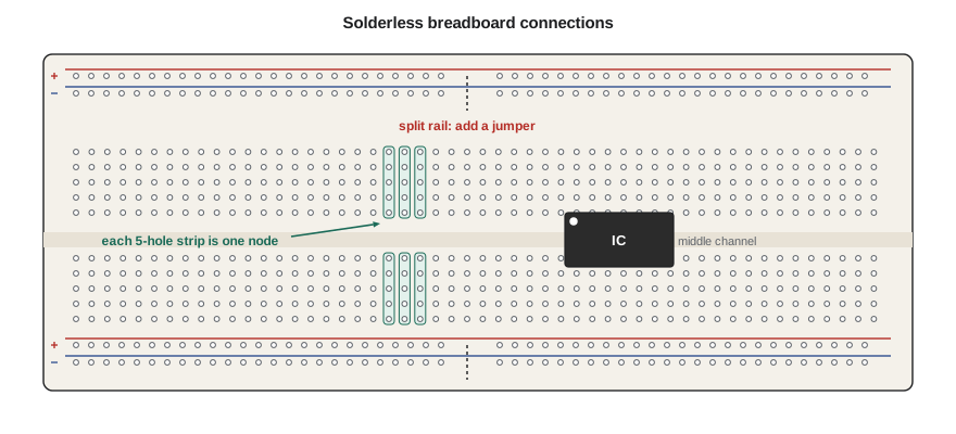
A solderless breadboard is a plastic block with rows of holes over spring-metal clips. In the main area, each short row of five holes on either side of the central channel is connected together, and the channel separates the two halves so that an integrated circuit in a dual in-line package can straddle it with each pin in its own row. Along the edges run long power rails, usually a red and a blue line on each side, connected along their length. On many full-size boards the rails are split in the middle, so the top half and bottom half of a rail are not connected unless you add a jumper. That split catches almost everyone once: half the circuit has no power and nothing about the board shows why.
Habits that make prototypes reliable
Plan the layout before inserting parts: place the integrated circuits first, oriented the same way with pin 1 marked, and arrange the rest to follow the signal flow from left to right, with power at the top rail and ground at the bottom. Use color-coded wire: red for positive supply, black or blue for ground, other colors for signals, so that a glance reveals a wire in the wrong place. Cut wires to length so they lie flat against the board instead of looping above it. Keep component leads short. Connect both ground rails together and both supply rails together, and run power to both halves of split rails. Mark polarized parts, electrolytic capacitors, diodes and LEDs, and double-check them before applying power, since a reversed electrolytic can fail violently.
Decoupling deserves its own rule. Every integrated circuit needs a ceramic capacitor, usually 100 nF, connected directly between its supply and ground pins with the shortest possible leads, plus one larger bulk capacitor, 10 to 100 µF, where power enters the board. When a logic gate switches, it draws a brief spike of current. Without a local capacitor, that current must come through the long, inductive supply wires, and the voltage at the chip's pin dips and rings. On a breadboard, missing decoupling causes erratic logic, oscillating op-amps and measurements that change when you touch a wire.
Worked problem
Why the LED flickered
Leo's first build works on the bench supply, but the LED flickers faintly when the input should be steady, and the Schmitt-trigger output shows short glitches on the scope. The buffer chip has no decoupling capacitor, and its supply comes through 25 cm of jumper wire. Estimate the dip when the buffer and LED switch, if the LED current of 10 mA rises in about 20 ns and the supply wire's inductance is about 1 µH per meter.
Show solution
- The wire is 0.25 m long, so its inductance is about 0.25 µH. The supply and ground paths together make roughly twice that, about 0.5 µH.
- \[v = L\frac{di}{dt} \approx 0.5 \times 10^{-6}\ \text{H} \times \frac{0.010\ \text{A}}{20 \times 10^{-9}\ \text{s}} = 0.25\ \text{V}\]
- A 0.25 V dip on a 5 V rail, plus ringing, can shift a Schmitt trigger's thresholds and produce glitches near a switching point.
Answer: Roughly a quarter of a volt of dip and ringing at each edge. Adding a 100 nF capacitor across the buffer's supply pins, and a 47 µF capacitor where the supply enters the board, removes the glitches; the capacitor supplies the brief current pulse locally, so the wire's inductance no longer matters.
Limits of the solderless breadboard
Breadboards are excellent for low-frequency analog circuits, slow logic and microcontroller experiments, but they have limits that you must keep in mind when interpreting measurements. Adjacent strips have a few picofarads of capacitance between them, and the long clips add inductance, so circuits above a few megahertz, fast edges and high-gain, high-impedance amplifiers misbehave. The spring contacts have a contact resistance of tens of milliohms that changes as parts are inserted and removed, and contacts wear and loosen over time, giving intermittent faults. Current is limited to about an ampere per contact, and the plastic softens with heat. Surface-mount parts need adapter boards. And because nothing is soldered, a bumped wire can quietly change the circuit between two measurements.
| Prototyping method | Strengths | Weaknesses | Good for |
|---|---|---|---|
| Solderless breadboard | Fast to build and change; no tools | Stray capacitance, loose contacts, low current, low frequency only | Low-frequency analog, slow logic, first experiments |
| Stripboard or perfboard | Soldered, durable, moderate frequency | Slower to change; layout planning needed | One-off tools, test fixtures, field prototypes |
| Dead-bug on a copper ground plane | Excellent ground, good at high frequency | Fragile; skill needed | RF and fast analog experiments |
| Evaluation board or prototype PCB | Close to the final design; surface-mount parts | Cost and lead time; harder to change | Verifying a design before production |
Choosing components for a prototype
Prototype components should be chosen with the final design in mind. Resistors come in standard series of preferred values: the E12 series has twelve values per decade, used with 10 % tolerance parts, and the E24 and E96 series have 24 and 96 values for 5 % and 1 % parts. Designing with values that exist avoids discovering at the end that a 4.32 kΩ resistor is needed. Power ratings matter too: a quarter-watt through-hole resistor on a breadboard can run hot without being noticed, and the surface-mount 0603 part on the final board may be rated for only a tenth of a watt. Capacitors should be chosen with the right dielectric: class I ceramics such as C0G for timing and filters, class II such as X7R for decoupling, and electrolytics for bulk storage, keeping in mind the DC bias effect on class II ceramics from lesson 8.
# Nearest preferred values, power checks and the divider-filter design for the button input
import math
E12 = [1.0, 1.2, 1.5, 1.8, 2.2, 2.7, 3.3, 3.9, 4.7, 5.6, 6.8, 8.2]
E24 = [1.0, 1.1, 1.2, 1.3, 1.5, 1.6, 1.8, 2.0, 2.2, 2.4, 2.7, 3.0,
       3.3, 3.6, 3.9, 4.3, 4.7, 5.1, 5.6, 6.2, 6.8, 7.5, 8.2, 9.1]

def nearest(value, series):
    dec = 10 ** math.floor(math.log10(value))
    cands = [s * dec for s in series] + [series[0] * dec * 10]
    return min(cands, key=lambda c: abs(c - value) / value)

# Divider: 24 V input to about 4.0 V at the Schmitt-trigger input, top resistor 47k
v_in, v_target, r_top = 24.0, 4.0, 47e3
r_bot_ideal = r_top * v_target / (v_in - v_target)
for name, ser in (("E12", E12), ("E24", E24)):
    rb = nearest(r_bot_ideal, ser)
    v = v_in * rb / (rb + r_top)
    print(f"{name}: bottom resistor {rb/1e3:.1f} k gives {v:.2f} V (ideal {r_bot_ideal/1e3:.2f} k)")

# Filter corner with 100 nF across the bottom resistor, using the E12 choice
rb = nearest(r_bot_ideal, E12)          # Leo picks the stocked 10 k value
rth = r_top * rb / (r_top + rb)
c = 100e-9
print(f"R_Th = {rth/1e3:.2f} k, time constant {rth*c*1e3:.2f} ms, corner {1/(2*math.pi*rth*c):.0f} Hz")

# Power in the top resistor at 24 V and in a 330-ohm LED resistor at 10 mA
p_top = (v_in - v_target) ** 2 / r_top
print(f"top resistor dissipates {p_top*1e3:.1f} mW; LED resistor {0.010**2*330*1e3:.1f} mW")E12: bottom resistor 10.0 k gives 4.21 V (ideal 9.40 k) E24: bottom resistor 9.1 k gives 3.89 V (ideal 9.40 k) R_Th = 8.25 k, time constant 0.82 ms, corner 193 Hz top resistor dissipates 8.5 mW; LED resistor 33.0 mW
The output shows that the ideal bottom resistor, 9.4 kΩ, is not in either series. The E12 choice of 10 kΩ gives 4.21 V; the E24 choice of 9.1 kΩ gives 3.89 V. Either is fine for a Schmitt trigger with a 5 V supply, and Leo picks 10 kΩ, a value already stocked for the board. The filter's time constant of about 0.8 ms rejects contact bounce and short noise spikes, and every resistor is far below its power rating.
Checking the build before power
The two minutes before applying power are the most productive in prototyping. Compare every connection with the schematic, ideally ticking off each net on a printout. Check the orientation of every polarized part and every integrated circuit. Measure the resistance between the supply rail and ground with the supply disconnected: a reading of a few ohms means a short, while tens of kilohms or more is normal for most small circuits, though a large discharged capacitor will show a reading that climbs as it charges. Set the supply's current limit low, as in lesson 5, and apply power while watching the current. Then measure the supply voltage at the chip pins themselves, not at the rail, before looking at any signals.
Worked problem
A resistance check before power-up
Before powering his second build, Leo measures the resistance between the 5 V rail and ground. The meter reads 1.8 Ω. With the Schmitt-trigger chip removed it reads 6.8 kΩ. What does this suggest?
Show solution
- A reading of a few ohms with the chip installed is a near short on the rail.
- With the chip removed, the reading is a plausible value for the remaining divider and LED circuit.
- So the fault is in the chip or its connections: inserted backwards, so its supply pins are swapped, or a solder bridge on its adapter board.
Answer: The chip was inserted rotated by 180°, putting its ground pin on the 5 V rail and its supply pin on ground. Powered, it would have drawn current through its protection diodes and probably failed. The resistance check found it in seconds.
From breadboard to soldered prototype
Once the circuit works on the breadboard, it is often moved to a soldered stripboard or a quick-turn prototype circuit board for longer tests, outdoor trials or a demonstration. Good soldering produces a smooth, shiny fillet that wets both the pad and the lead; a dull, balled or cracked joint is a likely future fault. Lead-free solder needs a hotter iron than the older tin-lead alloys. Flux fumes should be extracted. Keep a schematic marked with every change you make to the prototype, because the hand-written changes on a prototype are the most likely things to be forgotten when the production board is drawn.
Common mistakes
MistakeAssuming the power rails run the full length of the breadboard.
InsteadCheck for split rails and add jumpers; also connect the rails on both sides of the board.
MistakeLeaving out decoupling capacitors on a prototype.
InsteadPut 100 nF at every chip's supply pins and a bulk capacitor where power enters.
MistakeUsing long, looping jumper wires.
InsteadCut wires to length and keep leads short; long loops add inductance, capacitance and pickup.
MistakeTrusting a breadboard for fast or high-frequency circuits.
InsteadExpect stray capacitance and inductance to dominate above a few megahertz; use a ground-plane prototype.
MistakeApplying power without a resistance check and current limit.
InsteadMeasure rail-to-ground resistance and set a low current limit first.
Summary and key terms
- Breadboard strips of five holes form nodes, ICs straddle the central channel, and power rails along the edges are often split.
- Plan layouts, use color-coded wires cut to length, and double-check polarized parts.
- Every IC needs local decoupling; without it, switching currents through wire inductance cause dips and glitches.
- Breadboards suit low-frequency work; stray capacitance, contact resistance and current limits restrict them.
- Choose preferred values, adequate power ratings and suitable dielectrics with the final design in mind.
- Check connections, polarity and rail resistance before applying power with a current limit.
- Solderless breadboard
- A reusable board of spring contacts arranged in connected strips for building circuits without solder.
- Decoupling capacitor
- A capacitor placed close to a chip's supply pins to supply brief current pulses locally and stabilize its supply voltage.
- Preferred values
- Standard series of component values, such as E12, E24 and E96, spaced evenly on a logarithmic scale.
- Split rail
- A breadboard power rail divided into two unconnected halves.
- Stripboard
- A perforated board with parallel copper strips used for soldered prototypes.
- Bulk capacitor
- A larger capacitor where power enters a board, supplying slower changes in load current.
Practice problems
Work each problem on paper first, then reveal the answer to check.
How many holes are connected together in one strip of a typical breadboard's main area?
Show answer
Five.
A current changes by 50 mA in 10 ns through 0.3 µH of wiring. Estimate the voltage spike.
Show answer
L di/dt = 0.3 µH × 5 × 10⁶ A/s = 1.5 V.
Find the nearest E12 value to 5.0 kΩ.
Show answer
4.7 kΩ or 5.6 kΩ; 4.7 kΩ is closer in ratio.
A divider of 47 kΩ and 10 kΩ feeds a 100 nF capacitor. Find the filter time constant.
Show answer
R_Th ≈ 8.25 kΩ, so τ ≈ 0.82 ms.
Why is a solderless breadboard a poor choice for a 50 MHz oscillator?
Show answer
Stray capacitance and inductance of the contacts and wires dominate at that frequency.
What does a rail-to-ground reading of 0.5 Ω before power-up indicate?
Show answer
A short circuit, such as a reversed chip or a wiring error.
Lesson quiz · 5 questions
Score 60% or more to complete this lesson.
Create a free account to save your progress, take quizzes and earn a certificate.