
ELE-280 · Lesson 10 of 12 · 24 min
Debugging methodology
Every circuit you build will, at some point, not work. The difference between an engineer who fixes it in twenty minutes and one who is still poking at it after two days is rarely knowledge of the circuit; it is method. Debugging is a form of experiment: you have a hypothesis about what is wrong, you make a measurement that could prove it wrong, and you update. Doing that systematically, writing down what you find, and choosing measurements that cut the problem in half each time turns a frustrating hunt into a short, predictable search. This lesson sets out that method and the common faults it tends to find.
Leo's skills are about to be tested. Three prototype controller boards come back from the assembly house. Board 1 works. Board 2 powers up but none of the signal heads light. Board 3 works on the bench but resets randomly when the LED heads switch on outdoors. Amara gives him boards 2 and 3 and a notebook.
Start with the symptom, not the fix
The first step is to describe precisely what is wrong, because a vague symptom produces random guesses. 'Board 2 doesn't work' leads nowhere. 'Board 2 draws 85 mA at 24 V, the 5 V rail is correct, the microcontroller's status LED blinks normally, but none of the six signal-head outputs ever goes high' points straight at a small part of the design. Compare against a known-good reference wherever possible: board 1 is a working copy, and measuring the same points on both boards is often the fastest debugging technique of all. Write the symptom down, including what does work, because what works rules out large parts of the circuit.
Check the obvious first
A large share of faults are not subtle at all, and checking the boring things first saves hours. Is the board powered, at the right voltage, measured at the chip pins and not just at the connector? Is the ground connected? Is the oscilloscope probe compensated and set to the right attenuation? Is the generator's output turned on? Is the firmware the version you think it is? Is the cable plugged into the right connector? Are there visible problems: a part missing, rotated, scorched or bridged with solder? Experienced engineers develop a checklist of these quick checks and run it before forming any clever theory.
| Check | How | Typical finding |
|---|---|---|
| Supply voltages | Meter at the chip's supply pins, not the connector | Missing rail, regulator in current limit, high resistance in a connector |
| Supply current | Bench supply display or a series meter | Far too high (short, reversed part) or far too low (something not powered) |
| Visual inspection | Magnifier or microscope, good light | Solder bridges, missing or rotated parts, cracked joints |
| Temperature | Fingertip on cool parts, thermal camera | A part much hotter than its neighbors is often shorted or oscillating |
| Clocks and resets | Scope on the oscillator and reset pins | Oscillator not starting, reset held active |
| Instrument setup | Check the probe, attenuation, coupling and trigger | The circuit was fine; the measurement was wrong |
Divide and conquer
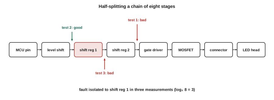
When the obvious checks pass, the most powerful technique is half-splitting. Think of the circuit as a chain of stages from input to output: for the signal heads, the microcontroller's shift-register outputs, then the shift registers, then the MOSFET gate drivers, then the MOSFETs, then the LED heads. Measure in the middle of the chain. If the signal is correct there, the fault is downstream; if not, it is upstream. Measure in the middle of the remaining half, and repeat. A chain of N stages needs only about log₂N measurements to locate the faulty stage, instead of up to N if you start at one end and work along.
Worked problem
Finding board 2's fault
On board 2, Leo scopes the signal-head chain. The microcontroller drives clock, data and latch lines to two cascaded shift registers, whose outputs drive six gate-driver inputs, then six MOSFET gates, then the head connectors. Where should he measure first, and how does the search go if the shift registers' data input toggles correctly but none of their outputs ever changes?
Show solution
- The microcontroller is clearly running, so start in the middle: the shift-register outputs. Their outputs never change, so the fault is at or before the shift registers.
- Next, the shift-register inputs: data, clock and latch all toggle at the right times, so the inputs are fine. The fault is in the shift registers themselves or their supply and control pins.
- Check the remaining pins of the first shift register: supply 5.0 V, ground 0 V, and the output-enable pin. Output-enable is active low and should be held at 0 V. It reads 5.0 V.
Answer: The output-enable pin is held high, so the shift-register outputs stay in their high-impedance state. On board 1, a 0 Ω jumper ties that pin to ground; on board 2 the jumper is missing, and the pull-up resistor holds the pin high. Fitting the jumper fixes the board. Four measurements, guided by half-splitting, found a missing part that was invisible on the schematic.
Make one change at a time, and write it down
When you suspect a cause, test it with a change that can only affect that cause, and then measure again. Changing three things at once, swapping a chip, adding a capacitor and reflashing the firmware, may fix the symptom without telling you which change mattered, and the next board will fail the same way. Keep a running log: the time, what you measured, what you saw, what you changed and the result. It feels slow, but it prevents the most common debugging trap, which is going in circles, re-measuring things you already checked an hour ago because you no longer remember the result. The log also becomes the start of the fault report that goes to the designers and the assembly house.
A good hypothesis must be testable, and a good test is one that could prove it wrong. 'Maybe it is noise' is not testable until you say what noise, from where, and what you would expect to see if it were the cause. 'The reset is caused by the 24 V rail dipping below the regulator's dropout when all six heads switch on' is testable: put a scope on the rail and the reset pin, trigger on the reset, and see whether the rail dips first.
Intermittent faults
Faults that come and go are the hardest to find, because the circuit may behave perfectly while you measure it. They usually come from one of a few causes: a marginal supply that dips under load, a poor solder joint or connector that opens with temperature or vibration, noise or ground bounce that crosses a threshold occasionally, a timing margin that fails at a particular temperature, or firmware that mishandles an unusual sequence of events. The strategy is to capture the event rather than wait for it: set the scope to Single with a trigger on the symptom, such as a reset line going low, and include the suspect signals on other channels. Stressing the circuit, by heating it with a hot-air tool, cooling it with freeze spray, tapping it or varying the supply voltage, often turns an intermittent fault into a repeatable one.
Worked problem
Board 3's random resets
Board 3 resets when all six LED heads switch on together, but only outdoors on a cold morning. On the bench at room temperature it never fails. Leo connects the scope to the 24 V input, the 5 V rail and the microcontroller's reset pin, triggers in Single mode on the reset pin going low, and chills the board with freeze spray. What should he look for, and what does the capture show?
Show solution
- If the rail theory is right, the 24 V input will sag when the heads switch on, the 5 V regulator will drop out, and the reset supervisor will fire after the 5 V rail falls below its threshold.
- The capture shows the 24 V input falling from 24 V to about 14 V for 3 ms as the heads switch on, while the 5 V rail stays at 5.0 V. The reset pin goes low 40 µs later anyway.
- The 5 V rail is fine, so the regulator theory is wrong. Zooming in shows a 1.5 V spike on the reset line itself at the moment the heads switch, coupled from the LED head wiring that runs alongside it.
- The reset line has a 100 kΩ pull-up and no filter capacitor, a high-impedance node easily disturbed by a fast current edge. When cold, the supervisor's threshold shifts slightly and the spike crosses it.
Answer: The fault is noise coupled into a high-impedance reset line, made worse by cold. Adding a 100 nF capacitor from reset to ground and staggering the head turn-on by a few milliseconds in firmware stops the resets. The first hypothesis was tested and rejected; the capture showed the real cause.
# Half-splitting: number of measurements to isolate one faulty stage among N
import math

def half_split(stages, faulty):
    lo, hi, tests = 0, len(stages) - 1, []
    # Invariant: signal is good at the input of stage lo and bad at the output of stage hi
    while lo < hi:
        mid = (lo + hi) // 2
        ok = mid < faulty               # output of stage mid is correct if the fault is later
        tests.append((stages[mid], "good" if ok else "bad"))
        if ok: lo = mid + 1
        else: hi = mid
    return stages[lo], tests

chain = ["MCU pin", "level shift", "shift reg 1", "shift reg 2", "gate driver",
         "MOSFET", "connector", "LED head"]
for f in (2, 6):
    found, tests = half_split(chain, f)
    print(f"fault in '{chain[f]}': found '{found}' after {len(tests)} tests: {tests}")
for n in (8, 16, 64, 1000):
print(f"{n:5d} stages: at most {math.ceil(math.log2(n))} half-split tests vs up to {n} sequential")fault in 'shift reg 1': found 'shift reg 1' after 3 tests: [('shift reg 2', 'bad'), ('level shift', 'good'), ('shift reg 1', 'bad')]
fault in 'connector': found 'connector' after 3 tests: [('shift reg 2', 'good'), ('MOSFET', 'good'), ('connector', 'bad')]
8 stages: at most 3 half-split tests vs up to 8 sequential
16 stages: at most 4 half-split tests vs up to 16 sequential
64 stages: at most 6 half-split tests vs up to 64 sequential
1000 stages: at most 10 half-split tests vs up to 1000 sequentialThe program finds a fault in either half of the eight-stage chain in three tests, and shows why the method matters more as systems grow: a thousand-stage chain, such as a long list of firmware commits or a set of wire connections, needs only ten tests. The same idea drives the bisect tools that software engineers use to find which change in a long history introduced a bug.
Common hardware faults
| Fault | Typical symptom | How to confirm |
|---|---|---|
| Solder bridge between pins | Short circuit, high current, odd logic levels | Visual inspection; resistance between adjacent pins |
| Cold or cracked joint | Intermittent operation, sensitivity to flexing or temperature | Inspection; press or heat the joint while monitoring |
| Part rotated or reversed | Hot part, short, no function | Compare orientation with the silkscreen and board 1 |
| Missing pull-up or pull-down | Floating input that behaves randomly | Measure the pin; touch it with a resistor to a rail |
| Oscillating amplifier | Hot op-amp, high supply current, fuzz on the output | Scope with a fast timebase and a short ground |
| Supply droop under load | Resets or errors when loads switch on | Scope on the rail triggered by the load change |
| Wrong component value | Wrong gain, time constant or threshold | Measure the part; compare with the bill of materials |
Common mistakes
MistakeChanging several things at once.
InsteadMake one change, measure, and record the result before the next change.
MistakeStarting with a clever theory instead of the basic checks.
InsteadCheck power, ground, clocks, resets, instrument setup and visual condition first.
MistakeMeasuring stages in order from one end of the chain.
InsteadHalf-split: measure in the middle and halve the search each time.
MistakeAssuming the measurement is right when the result is surprising.
InsteadCheck the probe, settings and ground; confirm with a second instrument or on a known-good board.
MistakeWaiting for an intermittent fault to happen while watching.
InsteadTrigger on the symptom in Single mode and stress the circuit to make the fault repeatable.
Summary and key terms
- Debugging is experiment: form a testable hypothesis, measure something that could prove it wrong, and update.
- Describe the symptom precisely, including what works, and compare with a known-good board.
- Run the quick checks first: power at the pins, current, inspection, temperature, clocks, resets and instrument setup.
- Half-splitting finds a faulty stage in about log₂N measurements.
- Change one thing at a time and keep a written log.
- Capture intermittent faults with triggered single acquisitions and make them repeatable by stressing the circuit.
- Half-splitting
- A search that tests the middle of a chain of stages and discards the half that is shown to be good, repeating until the fault is found.
- Known-good reference
- A working copy of a circuit used for comparison measurements.
- Intermittent fault
- A fault that appears only sometimes, often with temperature, vibration or particular load conditions.
- Testable hypothesis
- A proposed cause stated precisely enough that a measurement could show it to be wrong.
- Cold solder joint
- A poorly wetted joint that may conduct unreliably.
- Floating input
- A logic input connected to nothing that drives it, so its level is undefined.
Practice problems
Work each problem on paper first, then reveal the answer to check.
How many half-split tests at most are needed to find one faulty stage among 32?
Show answer
5.
Why is 'the circuit is noisy' a poor hypothesis?
Show answer
It does not say what noise, where it comes from, or what measurement would confirm or reject it.
A chip is much hotter than identical chips nearby. Name two likely causes.
Show answer
It may be inserted backwards or shorted, or an amplifier may be oscillating.
Give two ways to make an intermittent temperature-related fault repeatable.
Show answer
Freeze spray, hot air, a thermal chamber, or cycling the board between temperatures.
Board A works and board B does not. What is the quickest first comparison?
Show answer
Measure the same supply rails, currents and key signals on both boards.
Why should a debugging log include measurements that showed nothing wrong?
Show answer
They rule out parts of the circuit and prevent re-measuring them later.
Lesson quiz · 5 questions
Score 60% or more to complete this lesson.
Create a free account to save your progress, take quizzes and earn a certificate.