
ELE-210 · Lesson 8 of 12 · 22 min
Latches and flip-flops
Everything so far has been combinational: the outputs depended only on the present inputs. A pedestrian controller cannot work that way. When someone presses the walk button and lets go, the controller must remember the request until it can serve it. A tachometer must remember its count between pulses. Memory in digital circuits comes from feedback: connect a gate's output back to an input, and the circuit can hold a value on its own. This lesson builds the basic storage elements, starting with the SR latch, then the gated D latch, and finally the edge-triggered flip-flops that hold the state of almost every digital system. It also covers asynchronous set and clear inputs and the debouncing of mechanical switches.
Bistable circuits
Connect two inverters in a ring, the output of each driving the input of the other. If the first output is 1, the second is 0, which keeps the first at 1: the loop is stable. If the first output is 0, the loop is equally stable the other way. Such a circuit is bistable: it has two stable states and stays in whichever one it is in for as long as power is applied. This is one bit of memory. The cross-coupled inverters cannot be changed from outside, so useful storage elements replace the inverters with NOR or NAND gates whose extra inputs can force the state.
The SR latch
The SR latch is two cross-coupled NOR gates. The S (set) input forces the output Q to 1, the R (reset) input forces Q to 0, and when both are 0 the latch holds its previous value. The second output Q̄ is normally the complement of Q. The combination S = R = 1 is forbidden: it forces both outputs to 0, so Q and Q̄ are no longer complements, and when both inputs return to 0 together the final state depends on which gate is faster, which is unpredictable.
| S | R | Q (next) | Action |
|---|---|---|---|
| 0 | 0 | Q | Hold |
| 0 | 1 | 0 | Reset |
| 1 | 0 | 1 | Set |
| 1 | 1 | — | Forbidden (both outputs 0) |
A latch built from cross-coupled NAND gates works the same way but with active-low inputs, usually written S̄ and R̄: a 0 on S̄ sets, a 0 on R̄ resets, both at 1 hold, and both at 0 is forbidden. The NAND version is common because NAND is the natural CMOS gate.
Debouncing a switch
Mechanical contacts bounce. When the pedestrian button is pressed, the metal contacts touch, spring apart and touch again several times over a few milliseconds before settling. A counter or state machine connected directly would see several presses. A classic hardware cure uses a changeover (single-pole double-throw) switch and an SR latch: the moving contact pulls S low in one position and R low in the other (using a NAND latch). Bounces on one contact only repeat the same set or reset command, and the contact never bounces all the way back to the other terminal, so the latch output changes exactly once.
The Cedarline button is a simple single-contact switch, so Amara uses a different method: she samples the button with the system clock and accepts a change only after the input has stayed the same for 20 ms, measured by a small counter. This digital debouncing, done with the counters of lesson 9, is cheaper and is how most modern products handle buttons. Either way, the principle is the same: the circuit must remember the last accepted state and ignore brief changes.
The gated D latch
An SR latch responds to its inputs at any time, and the forbidden combination is a nuisance. The gated D latch fixes both problems. It has a data input D and an enable input, often labeled C, G or EN. When the enable is 1, the latch is transparent: Q follows D. When the enable is 0, the latch holds whatever value D had at the moment the enable fell. Internally, D drives S and D̄ drives R of an SR latch through AND gates controlled by the enable, so S and R can never both be 1.
Transparency is the D latch's strength and its weakness. It is useful for holding a value while something else reads it, and latches are used in some high-performance designs. But if the output of a latch feeds back, through some logic, to its own input while the enable is high, the signal can race around the loop several times during one enable pulse. A counter built from transparent latches would count an unpredictable number of steps per pulse. Synchronous design therefore uses flip-flops, which change only at an instant.
The edge-triggered D flip-flop
A D flip-flop samples its D input only at a clock edge, usually the rising edge, and holds that value until the next rising edge, whatever D does in between. The classic construction is a master-slave pair of D latches. The master is transparent when the clock is low and the slave is transparent when the clock is high. While the clock is low, the master follows D and the slave holds the old output. When the clock rises, the master closes, capturing D, and the slave opens, passing the captured value to Q. At no time is there a transparent path from D to Q, so feedback loops cannot race.
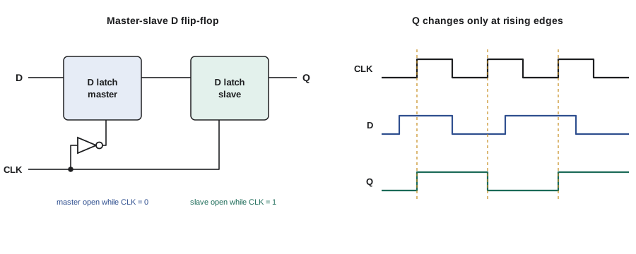
The schematic symbol of an edge-triggered flip-flop has a small triangle at the clock input, called the dynamic indicator. A bubble before the triangle means the flip-flop triggers on the falling edge. Datasheets and timing diagrams show the edge with an arrow. Lesson 11 adds the timing rules: D must be stable for a short setup time before the edge and a hold time after it, and Q changes after a clock-to-output delay.
# Simulate a transparent D latch and a rising-edge D flip-flop on the same inputs
clk = [0, 0, 1, 1, 0, 0, 1, 1, 0, 0, 1, 1, 0, 0]
d   = [0, 1, 1, 0, 0, 1, 0, 1, 1, 0, 0, 0, 1, 1]

latch_q, ff_q = 0, 0
latch, ff = [], []
prev_clk = 0
for c, x in zip(clk, d):
    if c:                       # latch is transparent while the enable (clock) is high
        latch_q = x
    if c and not prev_clk:      # flip-flop samples D only on a rising edge
        ff_q = x
    latch.append(latch_q); ff.append(ff_q)
    prev_clk = c

row = lambda name, v: print(f"{name:6s}" + "".join("_" if b == 0 else "#" for b in v))
row("CLK", clk); row("D", d); row("latch", latch); row("FF", ff)
print("latch output changes:", sum(a != b for a, b in zip(latch, latch[1:])),
" flip-flop output changes:", sum(a != b for a, b in zip(ff, ff[1:])))CLK __##__##__##__ D _##__#_##___## latch __#____###____ FF __####________ latch output changes: 4 flip-flop output changes: 2
JK and T flip-flops
Two other flip-flop types are worth knowing, although modern designs build almost everything from D flip-flops. The JK flip-flop is like an SR flip-flop without a forbidden state: J sets, K resets, J = K = 0 holds, and J = K = 1 toggles the output to its complement. The T (toggle) flip-flop has one input: T = 0 holds and T = 1 toggles at each clock edge. A T flip-flop with T tied to 1 divides the clock frequency by two, which makes it the natural element for binary counters (lesson 9).
| Type | Inputs | Behavior at the clock edge | Characteristic equation |
|---|---|---|---|
| D | D | Q takes the value of D | Q⁺ = D |
| JK | J, K | 00 hold, 01 reset, 10 set, 11 toggle | Q⁺ = JQ̄ + K̄Q |
| T | T | 0 hold, 1 toggle | Q⁺ = T ⊕ Q |
| SR | S, R | 00 hold, 01 reset, 10 set, 11 not allowed | Q⁺ = S + R̄Q (with SR = 0) |
Any flip-flop type can be made from a D flip-flop plus a little logic: put the characteristic equation in front of the D input. A T flip-flop is a D flip-flop with an XOR gate feeding D = T ⊕ Q. This is exactly what synthesis tools do, because programmable chips and standard-cell libraries are built around D flip-flops.
Excitation tables
When designing sequential circuits, the question is often reversed: given the present state Q and the desired next state Q⁺, what must the inputs be? The answer is an excitation table. For a D flip-flop it is trivial: D = Q⁺. For a JK flip-flop each transition allows a don't-care: to go from 0 to 0, J must be 0 and K does not matter; from 0 to 1, J = 1 and K does not matter; from 1 to 0, K = 1 and J does not matter; from 1 to 1, K = 0 and J does not matter. Those don't-cares can make the input logic smaller, which is why JK flip-flops were popular when designs were built from discrete chips.
| Q | Q⁺ | D | J | K | T |
|---|---|---|---|---|---|
| 0 | 0 | 0 | 0 | X | 0 |
| 0 | 1 | 1 | 1 | X | 1 |
| 1 | 0 | 0 | X | 1 | 1 |
| 1 | 1 | 1 | X | 0 | 0 |
Asynchronous preset and clear
Most flip-flops also have asynchronous inputs, often active-low, called preset (or set) and clear (or reset). They force Q to 1 or 0 immediately, without waiting for a clock edge, and override the clock and D inputs. They are used to put a system into a known state at power-up. A synchronous reset, by contrast, is just an input to the D logic that forces a 0 at the next clock edge. Both are common; the choice affects timing and how reset is released. Releasing an asynchronous reset close to a clock edge can cause problems, so good designs synchronize the release of reset to the clock.
The pedestrian controller must start in a safe state after a power failure: all signals red until the controller has checked itself. Amara connects the state register's asynchronous clear to a power-on reset circuit that holds it low for 100 ms after the supply becomes valid, and she makes sure that state 000 is decoded as all red rather than main-street green. Lesson 10 returns to this choice.
Metastability, briefly
A flip-flop is a bistable circuit, and any bistable circuit has a third, unstable balance point between its two stable states, like a ball balanced on the crest of a hill. If the D input changes too close to the clock edge, violating the setup or hold time, the flip-flop can be left near that balance point for an unpredictable time before falling one way or the other. During that time its output may sit at an invalid voltage or oscillate. This is metastability. It can never be eliminated, only made extremely unlikely, and it matters whenever a flip-flop samples a signal that is not synchronized to its clock, such as the pedestrian button. Lesson 11 shows the standard cure: a two-flip-flop synchronizer.
Worked problem
Choosing a storage element for the walk request
The walk request W from lesson 3 may be a short pulse that arrives at any time, but the controller's state machine only looks at it on clock edges. Design a storage circuit that remembers the request until the controller acknowledges it with a one-cycle signal ACK.
Show solution
- The request must be captured even if it is shorter than a clock period, so it should set a storage element directly: use W as the set input.
- The controller clears the request with ACK, so ACK is the reset.
- To keep the design synchronous, use a D flip-flop with next-state logic rather than an asynchronous SR latch: D = W + REQ·ACK̄, where REQ is the flip-flop output.
- A very short W pulse between clock edges could still be missed by a flip-flop, so W should come from the debounced, synchronized button, which lasts at least one clock period.
Answer: REQ⁺ = W + REQ·ACK̄ in a D flip-flop: the request sets the flag, which stays set until the controller acknowledges it.
The equation REQ⁺ = W + REQ·ACK̄ is the characteristic equation of a set-dominant SR flip-flop, built from a D flip-flop and two gates. This pattern, a flag that is set by an event and cleared by an acknowledgment, appears throughout digital systems: interrupt flags, error flags and handshake signals all work this way.
Common mistakes
MistakeApplying S = R = 1 to an SR latch.
InsteadThat combination is forbidden; use a D latch or flip-flop, or ensure S and R are never both active.
MistakeUsing a transparent latch where its output feeds back to its input.
InsteadUse an edge-triggered flip-flop so that each clock edge produces exactly one update.
MistakeConnecting a mechanical button directly to a counter.
InsteadDebounce it with a latch or a sampled timer so that one press counts once.
MistakeAssuming the asynchronous clear waits for the clock.
InsteadAsynchronous inputs act immediately and override the clock.
MistakeFeeding an unsynchronized input straight into several flip-flops.
InsteadSynchronize it first; different flip-flops may otherwise capture different values.
Summary and key terms
- Feedback creates bistable circuits that store one bit.
- An SR latch sets, resets or holds; S = R = 1 is forbidden.
- A gated D latch is transparent while enabled and holds when disabled.
- An edge-triggered D flip-flop samples D only at a clock edge; master-slave latches build it.
- JK and T flip-flops add toggle behavior; any type can be made from a D flip-flop plus logic.
- Excitation tables give the inputs needed for each transition; asynchronous preset and clear act immediately.
- Latch
- A level-sensitive storage element whose output can change whenever its enable is active.
- Flip-flop
- An edge-triggered storage element that changes state only at a clock edge.
- Transparent
- Describes a latch whose output follows its input while it is enabled.
- Characteristic equation
- An expression for a flip-flop's next state in terms of its inputs and present state.
- Excitation table
- A table giving the inputs needed to cause each possible state transition.
- Switch bounce
- The rapid opening and closing of mechanical contacts for a few milliseconds after they move.
- Metastability
- An unpredictable delay in a flip-flop settling to 0 or 1 after a timing violation.
Practice problems
Work each problem on paper first, then reveal the answer to check.
A NOR SR latch has Q = 0. The inputs go S = 1, R = 0, then S = 0, R = 0. What is Q?
Show answer
Q becomes 1 on the set and stays 1 during hold.
Write the characteristic equation of a D latch with enable G.
Show answer
Q⁺ = GD + ḠQ.
A JK flip-flop has Q = 1, J = 1, K = 1. What is Q after the clock edge?
Show answer
It toggles to 0.
Using the excitation table, what J and K are needed to take a JK flip-flop from 0 to 1?
Show answer
J = 1, K = X (don't care).
Build a T flip-flop from a D flip-flop.
Show answer
Feed D = T ⊕ Q.
A clock of 10 MHz drives a T flip-flop with T = 1. What frequency appears at Q?
Show answer
5 MHz: the output toggles once per clock cycle.
Lesson quiz · 5 questions
Score 60% or more to complete this lesson.
Create a free account to save your progress, take quizzes and earn a certificate.