
CMP-499 · Lesson 5 of 12 · 20 min
Interfaces and interface control documents
When capstone systems fail at integration, the cause is rarely a broken subsystem. It is usually a boundary between two subsystems that each work perfectly on their own: a byte order nobody agreed, a voltage level that drifts out of range in the cold, a message sent before the receiver is ready, a field interpreted in different units on each side. The TrailCount team had four people building four subsystems in parallel. The only way that could work was to define every boundary precisely, in writing, before anyone built anything that depended on it. This lesson is about those definitions: interface control documents.
What counts as an interface
An interface is any place where two elements exchange something: energy, data, force, heat or even light. Engineers usually group interfaces into a few kinds.
- Electrical: supply voltages and currents, logic levels, timing, connectors and pin assignments, grounding and protection.
- Data and protocol: message formats, encodings, byte order, rates, sequencing, error handling, versioning.
- Mechanical: mounting holes, clearances, cable routing, sealing surfaces, mass.
- Thermal and environmental: heat flow between elements, the heater's effect on the battery, condensation paths.
- Human: the installer's view of the mounting bracket, the status indicator, the service procedure, the dashboard's presentation.
External interfaces connect the system to the outside world: the radio link to Northway's gateway, the dashboard's data feed, the post on which the node mounts, and, less obviously, the trail users, whose speed and spacing are inputs the system must handle. Internal interfaces connect elements within the system.
Finding every interface: the N-squared diagram
Lucas found the team's interfaces systematically with an N-squared diagram. The subsystems sit on the diagonal of a square grid. A cell in row i and column j records what subsystem i sends to subsystem j. Reading across a row shows everything a subsystem produces; reading down a column shows everything it needs. Empty cells are as informative as full ones: they confirm that two elements have no direct dependency, and a surprising empty cell often reveals a missing interface.
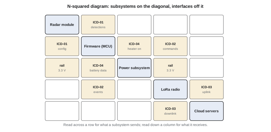
The first version of the diagram had an empty cell from the firmware to the power subsystem. When Keisha drew it, she realized the heater needed a control signal from the firmware, which needed the cell temperature from the power subsystem. Neither had been specified. That gap became ICD-04. Finding it on paper in week 9 cost an hour; finding it on the alpha board in week 14 would have cost a board revision.
The interface control document
An interface control document (ICD) is the agreed, authoritative definition of one interface, owned jointly by the leads on both sides. When an ICD exists, a developer on one side can build and test against it without waiting for the other side, and an integration failure can be traced to whichever side departs from the document. TrailCount had four ICDs.
| ICD | Between | Main content |
|---|---|---|
| ICD-01 | Radar module and firmware | UART at 921,600 bit/s, frame format of the module's detection list, configuration commands, start-up sequence, error codes |
| ICD-02 | Firmware and LoRa module | SPI or serial command set, join procedure, transmit and receive events, timeouts and retries |
| ICD-03 | Node and cloud | Uplink payload format, port numbers, downlink commands, versioning, decoder behavior |
| ICD-04 | Power subsystem and firmware | Fuel-gauge registers over I2C, cell temperature, charger status, heater enable, low-battery thresholds |
Each ICD followed the same outline: purpose and scope; the two sides and their owners; the physical layer (connector, pins, voltage levels, timing); the data layer (message formats with every field's name, width, units, range, resolution and byte order); sequences and timing, including start-up and error recovery; performance (rates, latency, maximum message size); a list of open issues; and a revision history. Tables are better than prose for message formats, and timing diagrams are better than prose for sequences.
Specifying a data format precisely
The uplink payload in ICD-03 is a good example of how much detail an apparently simple interface needs. Each 15-minute uplink carries four counts (pedestrians and cyclists, in each direction), the battery voltage, the enclosure temperature and a byte of flags. An ICD that said only that much would leave a dozen questions open. How wide is each count? Signed or unsigned? Little-endian or big-endian? Battery voltage in millivolts or tenths of a volt? Temperature in degrees with what offset, since the node must report −30 °C? What does each flag bit mean? What happens if a count exceeds its maximum? How does the decoder know which version of the format it is reading?
The team's answers went into a field table. The first byte holds a 4-bit format version and 4 flag bits (low battery, heater on, radar fault, clock not synchronized). The four counts are unsigned 16-bit integers, little-endian, saturating at 65,535 rather than wrapping. Temperature is sent as degrees Celsius plus 40, in one unsigned byte, covering −40 °C to +215 °C in steps of 1 °C. Each choice was written down with its reason.
Checking the format against the radio's limits
An interface definition must also respect the limits of the medium. LoRaWAN in North America uses the 902 to 928 MHz band under the US915 channel plan, which is also used in Canada. The regional parameters limit each transmission to a dwell time of 400 ms. A packet's time on air depends on the payload length and the spreading factor: higher spreading factors reach farther but take longer. LoRaWAN adds 13 bytes of its own to each application payload: a header byte, a 4-byte device address, a control byte, a 2-byte frame counter, a port byte and a 4-byte message integrity code.
import math, struct
# Uplink payload from ICD-03 (node to network server), little-endian.
# Rev A: flags, four 16-bit counts, battery in mV (16 bits), temperature + 40 C
# Rev B: battery sent as (mV - 2000) / 10 in one byte, saving a byte
REV = {'A': '<BHHHHHB', 'B': '<BHHHHBB'}
def pack(rev, flags, ped_in, ped_out, bike_in, bike_out, batt_mv, temp_c):
    batt = batt_mv if rev == 'A' else round((batt_mv - 2000) / 10)
    return struct.pack(REV[rev], flags, ped_in, ped_out, bike_in, bike_out, batt, temp_c + 40)
def unpack(rev, b):
    f, pi, po, bi, bo, batt, t = struct.unpack(REV[rev], b)
    mv = batt if rev == 'A' else 2000 + 10 * batt
    return dict(flags=f, ped_in=pi, ped_out=po, bike_in=bi, bike_out=bo, batt_mv=mv, temp_c=t - 40)

def time_on_air(pl, sf, bw=125e3, cr=1, preamble=8, header=True, crc=True):
    """LoRa packet duration in seconds (formula from the radio maker's design guide)."""
    de = 1 if (sf >= 11 and bw == 125e3) else 0      # low data rate optimization
    ih = 0 if header else 1
    tsym = 2 ** sf / bw
    n = 8 + max(math.ceil((8 * pl - 4 * sf + 28 + 16 * crc - 20 * ih) / (4 * (sf - 2 * de))) * (cr + 4), 0)
    return (preamble + 4.25) * tsym + n * tsym

for rev in 'AB':
    msg = pack(rev, 0x11, 37, 41, 12, 9, 3298, -18)
    print(f"Rev {rev}: {len(msg)} bytes: {msg.hex(' ')}")
    print('  decoded:', unpack(rev, msg))
    phy = len(msg) + 13      # LoRaWAN header, port and integrity code add 13 bytes
    for sf in (7, 10):
        t = time_on_air(phy, sf)
        ok = 'within' if t <= 0.400 else 'over'
print(f" SF{sf}: {t * 1000:6.1f} ms ({ok} the 400 ms dwell limit)")Rev A: 12 bytes: 11 25 00 29 00 0c 00 09 00 e2 0c 16
decoded: {'flags': 17, 'ped_in': 37, 'ped_out': 41, 'bike_in': 12, 'bike_out': 9, 'batt_mv': 3298, 'temp_c': -18}
SF7: 61.7 ms (within the 400 ms dwell limit)
SF10: 411.6 ms (over the 400 ms dwell limit)
Rev B: 11 bytes: 11 25 00 29 00 0c 00 09 00 82 16
decoded: {'flags': 17, 'ped_in': 37, 'ped_out': 41, 'bike_in': 12, 'bike_out': 9, 'batt_mv': 3300, 'temp_c': -18}
SF7: 61.7 ms (within the 400 ms dwell limit)
SF10: 370.7 ms (within the 400 ms dwell limit)Revision A of the payload, with battery voltage as a 16-bit value in millivolts, was 12 bytes long. At spreading factor 7 it takes 62 ms, but the trail site is about 1.6 km from Northway's nearest gateway through trees, and Lucas's range test showed that the node would sometimes need spreading factor 10. At SF10 the 25-byte packet takes 412 ms, just over the limit. The fix was not in the radio but in the interface. Revision B sends the battery voltage as one byte: (millivolts − 2,000) / 10, covering 2.00 V to 4.55 V in 10 mV steps, which is more than enough for a cell that operates between about 2.5 V and 3.65 V. The payload shrinks to 11 bytes and the SF10 packet to 371 ms. The decoded battery reading changes from 3,298 mV to 3,300 mV, well within the accuracy the fuel gauge can deliver anyway.
Worked problem
Choosing a resolution for a one-byte field
The enclosure temperature must cover −40 °C to +85 °C. If it is sent in one unsigned byte with an offset, what is the finest resolution possible, and what offset should be used?
Show solution
- One byte holds 256 values, from 0 to 255. The span to cover is
- \[85 - (-40) = 125\ ^\circ\text{C}\]
- The finest resolution that fits is the span divided by the number of steps:
- \[\Delta T = \frac{125}{255} \approx 0.49\ ^\circ\text{C}\]
- Using 0.5 °C steps gives 251 values for the span. An offset of 40 °C maps −40 °C to code 0: code = 2 × (T + 40).
- The team kept 1 °C steps with an offset of 40, because the heater logic needs only whole degrees and the simpler encoding is easier to read in raw logs.
Answer: About 0.5 °C resolution with code = 2(T + 40); the team chose 1 °C steps with code = T + 40 for simplicity.
Versioning and compatibility
Interfaces change. The payload changed from revision A to revision B in week 11, and it would change again if a later product added a battery heater duty field or a third mode such as e-scooters. Two habits keep changes from breaking deployed systems. First, every message carries a version number, so the decoder can handle old and new formats side by side. The cloud decoder in ICD-03 reads the version nibble and selects the matching layout; an unknown version is stored raw and raises an alert rather than producing garbage counts. Second, the team distinguished compatible changes (adding an optional field at the end, which old decoders can ignore) from incompatible ones (changing the width of an existing field), and required an ICD revision with both owners' agreement for either.
Electrical interfaces and timing
Data formats get most attention, but electrical details cause many integration failures. ICD-01 specified that the radar module's UART runs at 3.3 V logic, that the module needs 1.8 s after power-up before it accepts commands, that it draws an inrush current of up to 1.2 A for a few milliseconds when its transmitter starts, and that its interrupt line is active low with an open-drain output requiring a pull-up on the main board. Each of these came from the datasheet, and two of them were wrong in the team's first schematic. The inrush current would have caused the regulator to dip and reset the microcontroller, a classic integration bug that the ICD review caught before the alpha board was ordered.
Timing belongs in the ICD too. The firmware must read a complete detection frame from the module before the next one starts, 100 ms later. At 921,600 bit/s with ten bits per byte on the wire, a maximum frame of 1,200 bytes takes about 13 ms, comfortably within the period. But if the firmware is busy with a radio transmission when the frame arrives, it must buffer the bytes by direct memory access rather than rely on a polling loop. The ICD states the worst case, and the firmware design in Amira's module specification shows how it is met.
Owning and reviewing interfaces
An ICD needs an owner on each side and a clear process for change. In the TrailCount team, the two subsystem leads on either side of an interface co-own its ICD; Lucas, as project manager, keeps the master list and checks that every ICD revision appears in the change log. ICDs are reviewed at the preliminary design review for completeness and at the critical design review for detail. During integration, every defect is classified as either a departure from an ICD, in which case the departing side fixes it, or a gap or error in an ICD, in which case the document is revised and both sides check their work.
The external interface to Northway's cloud needed one more step. Dana Okoye owns the network and application servers, so ICD-03 was co-owned by Lucas and Dana. Dana asked for one change that the team had not considered: a unique port number for TrailCount uplinks, so that her decoder could route them without looking up the device type. That small request is typical of what external interface reviews reveal: the other side has constraints the team cannot see.
Common mistakes
MistakeDescribing a message format in prose such as four counts and the battery voltage.
InsteadSpecify every field's name, width, signedness, units, range, resolution, byte order and overflow behavior in a table.
MistakeLeaving interfaces to be sorted out at integration.
InsteadFind every interface early with an N-squared diagram and agree an ICD for each before building.
MistakeIgnoring the medium's limits when designing a payload.
InsteadCheck message sizes against bandwidth, dwell time and duty limits, and change the interface if needed.
MistakeChanging a format on one side without telling the other.
InsteadVersion every message, distinguish compatible from incompatible changes, and revise the ICD with both owners' agreement.
MistakeCopying electrical details from a datasheet summary.
InsteadCheck start-up delays, inrush current, logic levels and output types, and put them in the ICD with references.
Summary and key terms
- Interfaces carry energy, data, force, heat or information between elements, and most integration failures happen at them.
- An N-squared diagram finds every interface systematically; unexpected empty cells reveal missing ones.
- An interface control document is the jointly owned, authoritative definition of one interface, covering physical, data, timing and error behavior.
- Data formats need every field's width, units, range, resolution, byte order and overflow behavior.
- Interfaces must respect the medium's limits; the TrailCount payload shrank to 11 bytes to stay under the 400 ms dwell limit at SF10.
- Version every message, review ICDs at design reviews, and classify integration defects as departures from or errors in an ICD.
- Interface
- A boundary across which two elements exchange energy, data, force, heat or information.
- Interface control document (ICD)
- The agreed, controlled definition of one interface, owned by both sides.
- N-squared diagram
- A grid with subsystems on the diagonal and their interfaces in the off-diagonal cells.
- Byte order
- The order in which the bytes of a multi-byte value are sent or stored, little-endian or big-endian.
- Time on air
- The duration of one radio transmission, set by payload length and modulation settings.
- Dwell time
- The maximum time a transmitter may stay on one channel in a single transmission.
- Spreading factor
- A LoRa setting that trades data rate for sensitivity and range.
- Backward compatibility
- The ability of a newer version of an interface to work with older implementations.
Practice problems
Work each problem on paper first, then reveal the answer to check.
Pack the value 3,298 as an unsigned 16-bit little-endian integer. Which bytes are sent, in order?
Show answer
3,298 = 0x0CE2, so the bytes are E2 then 0C.
How many cells does an N-squared diagram for six subsystems have off the diagonal?
Show answer
6 × 6 − 6 = 30 cells.
A count field is 8 bits and a busy summer interval sees 300 passages. What goes wrong, and what should the ICD specify?
Show answer
300 exceeds 255; the field must be wider, and the ICD should state whether counts saturate or wrap when they overflow.
Why did TrailCount send battery voltage as (mV − 2,000) / 10 rather than in millivolts?
Show answer
It fits in one byte, which shortens the payload to 11 bytes and keeps the SF10 packet under the 400 ms dwell limit, with resolution still finer than the gauge's accuracy.
Lesson quiz · 5 questions
Score 60% or more to complete this lesson.
Create a free account to save your progress, take quizzes and earn a certificate.