
CIV-270 · Lesson 7 of 12 · 21 min
The Bernoulli equation and its limits
During a power failure two summers ago, the Northside clearwell had to be partly drained without pumps, and Ray Mendoza's crew rigged a 100 mm siphon hose over the clearwell wall. It worked, but only after they lowered the hose crest: with the crest too high above the water, the flow stopped and the hose filled with bubbles. Jun Park wanted to know why. The answer lies in the most famous equation in fluid mechanics, the Bernoulli equation, which relates pressure, velocity and elevation along a streamline. It is powerful, simple and frequently misused, so this lesson pays as much attention to its limits as to its uses.
Newton's second law along a streamline
Consider a small fluid particle moving along a streamline in steady flow. Measure distance \(s\) along the streamline. The forces acting along the streamline are the pressure difference across the particle's ends and the component of its weight; we neglect viscous forces. Newton's second law, with the particle's acceleration along the streamline equal to \(V\,dV/ds\) in steady flow (the convective acceleration of Lesson 5), gives the Euler equation along a streamline.
For an incompressible fluid, every term can be integrated along the streamline. The result is the Bernoulli equation: along a streamline in steady, incompressible, frictionless flow, the sum of pressure, kinetic energy per unit volume and potential energy per unit volume stays constant.
Dividing by \(\gamma = \rho g\) gives the head form, in which every term is a length. The pressure head \(p/\gamma\), the velocity head \(V^2/(2g)\) and the elevation head \(z\) add up to the total head \(H\), which stays constant along the streamline. Engineers working with pumps and pipelines almost always use the head form, because heads can be drawn directly on a profile of the pipeline.
Static, dynamic and stagnation pressure
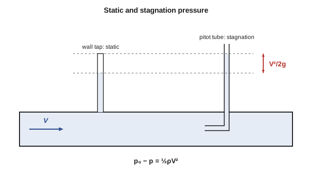
In the pressure form, \(p\) is the static pressure, the pressure a gauge moving with the fluid would read, and the one measured at a tap flush with the pipe wall. The term \(\tfrac{1}{2}\rho V^2\) is the dynamic pressure. Their sum, plus the hydrostatic term, is the total pressure. At a stagnation point, where the fluid comes to rest on the nose of a body, the velocity term converts entirely into pressure, and the local stagnation pressure equals static plus dynamic pressure.
This is the principle of the pitot tube, an open tube facing upstream, which reads the stagnation pressure, combined with a static tap, which reads the static pressure. The difference gives the velocity. Pitot-static probes measure aircraft airspeed, and in water systems a pitot rod inserted through a corporation stop measures the velocity at points across a large main, from which the flow rate can be found. In the 600 mm main, a differential of 1.28 kPa corresponds to 1.60 m/s.
Applying the Bernoulli equation
The equation is used between two points on the same streamline, often a free surface and a jet or outlet. The standard steps are: draw the streamline, choose points where as much as possible is known, pick an elevation datum, write the equation, and simplify. At a large reservoir's free surface, velocity is negligible and pressure is atmospheric. At a free jet discharging to the atmosphere, the pressure across the jet is atmospheric. Using gauge pressure makes those atmospheric terms zero.
One famous result follows immediately. For a tank draining through a small hole a depth \(h\) below the surface, apply Bernoulli from the surface, where \(p = 0\) gauge and \(V \approx 0\), to the jet, where \(p = 0\) gauge: the jet velocity is \(\sqrt{2gh}\), the speed a stone gains falling through height \(h\). This is Torricelli's result, used in Lesson 6. Real openings deliver somewhat less flow, because friction slows the jet slightly and the jet contracts after it leaves a sharp-edged hole; the discharge coefficient of about 0.6 covers both effects.
Worked problem
The siphon over the clearwell wall
The siphon hose has a diameter of 100 mm (3.94 in). Its outlet discharges freely 3.0 m (9.8 ft) below the clearwell water surface, and its crest is 4.0 m (13.1 ft) above the surface. Neglecting friction, find the velocity, the flow rate and the absolute pressure at the crest. The barometer reads 97.4 kPa.
Show solution
- Surface (1) to outlet (3), datum at the surface: \(0 + 0 + 0 = 0 + V^2/(2g) - 3.0\), so \(V = \sqrt{2(9.81)(3.0)} = 7.67\ \text{m/s}\).
- \(Q = VA = 7.67\,\pi(0.100)^2/4 = 0.0603\ \text{m}^3/\text{s} = 60.3\ \text{L/s}\).
- Surface to crest (2), in absolute pressure: \(p_{\text{atm}} = p_2 + \tfrac{1}{2}\rho V^2 + \rho g(4.0)\). The hose has the same diameter throughout, so \(V_2 = 7.67\ \text{m/s}\).
- \(p_2 = p_{\text{atm}} - 998(7.67)^2/2 - 998(9.81)(4.0) = p_{\text{atm}} - 29.4 - 39.2\ \text{kPa}\).
Answer: The crest pressure is about 28.9 kPa absolute (4.2 psia), well below atmospheric but above water's vapor pressure of 2.3 kPa at 20 °C. Raising the crest lowers this pressure; once it nears the vapor pressure, dissolved air and then vapor come out of solution and the siphon breaks. That is what happened to Ray's first attempt.
# Bernoulli along a streamline: a siphon over the clearwell wall and a pitot probe
import math
g, rho = 9.81, 998.0
patm, pv = 97.4e3, 2.34e3       # Pa: barometer at the station, pressure at which water boils at 20 C

# Siphon: free surface at z = 0, crest at z = +zc, discharge at z = -zd
def siphon(zc, zd):
    V = math.sqrt(2 * g * zd)                 # Bernoulli from surface to outlet
    p_crest = patm - rho * g * zc - rho * V**2 / 2
    return V, p_crest

d = 0.10
for zc in (2.0, 4.0, 6.0):
    V, pc = siphon(zc, 3.0)
    Q = V * math.pi * d**2 / 4
    flag = "close to boiling pressure" if pc < 4 * pv else "ok"
    print(f"crest {zc:3.1f} m: V = {V:4.2f} m/s, Q = {Q*1000:5.1f} L/s, p_crest = {pc/1000:6.1f} kPa abs  {flag}")

# Highest crest before the water starts to boil (outlet 3 m below)
V = math.sqrt(2 * g * 3.0)
zmax = (patm - pv - rho * V**2 / 2) / (rho * g)
print(f"Maximum crest height with a 3.0 m drop: {zmax:.2f} m")

# Pitot-static probe in the 600 mm main: dynamic pressure from a differential gauge
for dp in (0.5e3, 1.28e3, 2.0e3):
    V = math.sqrt(2 * dp / rho)
print(f"pitot dp = {dp/1000:4.2f} kPa -> V = {V:.2f} m/s")crest 2.0 m: V = 7.67 m/s, Q = 60.3 L/s, p_crest = 48.4 kPa abs ok crest 4.0 m: V = 7.67 m/s, Q = 60.3 L/s, p_crest = 28.9 kPa abs ok crest 6.0 m: V = 7.67 m/s, Q = 60.3 L/s, p_crest = 9.3 kPa abs close to boiling pressure Maximum crest height with a 3.0 m drop: 6.71 m pitot dp = 0.50 kPa -> V = 1.00 m/s pitot dp = 1.28 kPa -> V = 1.60 m/s pitot dp = 2.00 kPa -> V = 2.00 m/s
The program shows that the flow rate does not depend on the crest height at all, in this frictionless model, while the crest pressure falls by about 9.8 kPa for every meter of extra height. It also computes the highest workable crest, about 6.7 m above the water surface with a 3 m drop at the station's elevation. In practice the limit is lower, because dissolved air comes out of solution well above the vapor pressure and because friction in the hose lowers the pressure further. Field crews keep siphon crests below about 5 m.
The energy grade line and hydraulic grade line
Plotting heads along a pipeline makes Bernoulli visual. The energy grade line (EGL) is a line at height \(H = p/\gamma + V^2/(2g) + z\) above the datum. The hydraulic grade line (HGL) lies one velocity head below it, at \(p/\gamma + z\). The HGL is the level to which water would rise in a piezometer tube tapped into the pipe at that point. Wherever the pipe rises above the HGL, the pressure inside is below atmospheric, a warning sign for air entry, collapse of thin-walled pipe or cavitation.
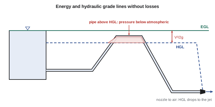
In the frictionless flow assumed by Bernoulli, the EGL is horizontal. In a real pipe it slopes downward in the direction of flow because friction converts mechanical energy into heat, and it jumps up at a pump and drops at a turbine. Lessons 10 to 12 add those effects. Experienced engineers sketch the EGL and HGL for every pipeline, because the sketch shows at a glance where pressures are high, where they are dangerously low, and where an air-release valve is needed.
When Bernoulli applies, and when it does not
The Bernoulli equation rests on four assumptions, and each can fail. The flow must be steady; during a valve closure or pump start, an extra unsteady term appears. The fluid must be incompressible, which is fine for liquids and for gases below a Mach number of about 0.3. The flow must be frictionless, which is reasonable over short distances in smooth, accelerating flows, such as through a nozzle or contraction, but poor over long pipes or through separated flows. And the equation holds along a single streamline, unless the flow is irrotational, in which case the constant is the same throughout.
Bernoulli also applies only where no shaft work or heat transfer occurs between the two points. It cannot be applied across a pump, a turbine or a fan. And it fails badly in regions of flow separation: downstream of a sudden enlargement, behind a partly closed valve, or in the wake of a bluff body. There, large eddies dissipate mechanical energy, and the pressure does not recover as the equation predicts. The energy equation of Lesson 10, with its head-loss term, handles these cases.
A common misconception deserves mention. It is often said that an aircraft wing generates lift because air over the curved top must travel farther in the same time and therefore goes faster. The conclusion that the top flow is faster is true, but the reasoning is false: the air over the top arrives at the trailing edge well before the air beneath it. Lift comes from the wing turning the flow downward, and Bernoulli correctly relates the resulting velocity and pressure differences, but it does not by itself explain why the velocities differ.
| Situation | Bernoulli between the points? | Reason |
|---|---|---|
| Reservoir surface to a nozzle jet | Yes | Short, accelerating, nearly frictionless flow |
| Across a venturi contraction | Yes, with a coefficient near 0.98 | Smooth acceleration, small losses |
| Pump inlet to pump outlet | No | Shaft work is added |
| Along 2 km of main | No | Friction losses are significant |
| Across a sudden enlargement | No | Separation and eddies dissipate energy |
| During rapid valve closure | No | Flow is unsteady |
Common mistakes
MistakeApplying Bernoulli across a pump, turbine or fan.
InsteadUse the energy equation with pump or turbine head (Lesson 10).
MistakeApplying Bernoulli over long pipes or through separated flows.
InsteadInclude head losses; Bernoulli assumes no friction.
MistakeMixing gauge and absolute pressure at the two points.
InsteadUse one reference; use absolute pressure for cavitation checks.
MistakeTaking velocity at a reservoir surface as large.
InsteadA large free surface moves so slowly that its velocity head is negligible.
MistakeAssuming the HGL and EGL are the same.
InsteadThe HGL lies one velocity head, V²/(2g), below the EGL.
Summary and key terms
- The Bernoulli equation, p + ½ρV² + ρgz = constant, holds along a streamline in steady, incompressible, frictionless flow.
- In head form, p/γ + V²/(2g) + z = H, the total head.
- Stagnation pressure equals static plus dynamic pressure; a pitot tube measures velocity from their difference.
- Torricelli's result: a jet from a hole a depth h below a free surface has V = √(2gh).
- The EGL is at the total head; the HGL is one velocity head lower; pipe above the HGL is below atmospheric pressure.
- Bernoulli fails across machines, over long pipes, in separated flows and in unsteady flow.
- Bernoulli equation
- p + ½ρV² + ρgz = constant along a streamline for steady, incompressible, frictionless flow.
- Static pressure
- The pressure in a flowing fluid measured by a tap flush with the wall.
- Dynamic pressure
- The kinetic-energy term ½ρV².
- Stagnation pressure
- The pressure reached where a flow is brought to rest without losses.
- Pitot tube
- A tube facing upstream that measures stagnation pressure.
- Velocity head
- The kinetic energy per unit weight, V²/(2g).
- Total head
- The sum of pressure, velocity and elevation heads.
- Energy grade line
- A line plotted at the total head along a pipeline.
- Hydraulic grade line
- A line plotted at the pressure plus elevation head; the level water would reach in a piezometer.
- Siphon
- A pipe that carries liquid over a high point and down to a lower outlet, with sub-atmospheric pressure at its crest.
Practice problems
Work each problem on paper first, then reveal the answer to check.
A pitot-static probe in a water main shows a differential of 3.2 kPa. Find the velocity.
Show answer
V = √(2 × 3200/998) = 2.53 m/s.
Water leaves a tank through a small hole 2.5 m below the surface. Find the ideal jet velocity.
Show answer
V = √(2 × 9.81 × 2.5) = 7.0 m/s.
A nozzle reduces a 100 mm hose to a 25 mm outlet discharging to air at 18 L/s. Find the gauge pressure in the hose, neglecting losses.
Show answer
V₁ = 2.29 m/s, V₂ = 36.7 m/s; p₁ = 998(36.7² − 2.29²)/2 = 668 kPa.
At a point in a pipe the pressure head is 12 m and the velocity is 3 m/s. How far below the EGL is the HGL?
Show answer
V²/(2g) = 0.46 m.
Explain why the siphon flow rate in the program does not change with crest height.
Show answer
In frictionless flow the velocity depends only on the drop from the surface to the outlet.
In the program, change the outlet drop to 5.0 m. What is the new maximum crest height?
Show answer
About 4.7 m: the higher velocity uses up more of the available pressure.
Lesson quiz · 5 questions
Score 60% or more to complete this lesson.
Create a free account to save your progress, take quizzes and earn a certificate.