
CIV-241 · Lesson 7 of 12 · 22 min
Geologic maps and structures
Rocks are rarely found in the flat, horizontal layers in which sediments were first deposited. Plate movements tilt, fold, fracture and displace them, producing geologic structures that control where rock types appear at the surface, how deep a given layer lies beneath a site, and where weak zones and water paths run. A geologic map records this information in two dimensions, and a trained reader can turn it into a three-dimensional picture of the ground. For civil engineers, reading geologic maps and understanding basic structures are essential skills for desk studies, route selection and the interpretation of boreholes.
Strike and dip
The orientation of any planar feature, such as a bedding plane, joint, fault or foliation, is described by its strike and dip. Strike is the compass direction of a horizontal line on the plane, the line along which the plane would meet a horizontal water surface. Dip is the angle between the plane and the horizontal, measured perpendicular to the strike, together with the direction in which the plane slopes down. A bed with strike 040° and dip 30° to the southeast is written 040/30 SE. Many engineers prefer the dip direction and dip notation, which gives the azimuth of the steepest downward direction followed by the dip angle, for example 130/30. This notation is unambiguous and is used by most slope stability software.
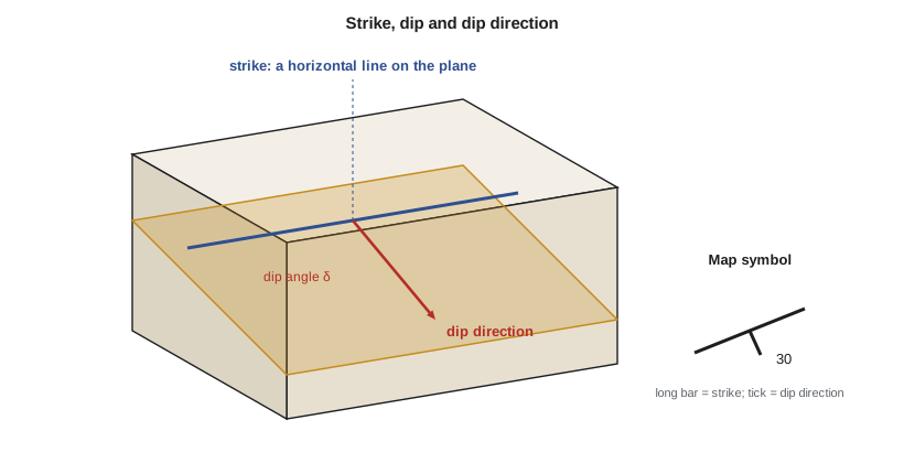
On geologic maps, strike and dip are shown by a T-shaped symbol: the long bar is parallel to strike, the short tick points in the dip direction, and the dip angle is written beside it. Special symbols show horizontal and vertical beds, overturned beds and foliation. Field measurements are made with a compass-clinometer, now often supplemented by smartphone applications and by measurements picked from photogrammetric or lidar models of rock faces.
Apparent dip and true thickness
A vertical section, such as a road cut, tunnel wall or cross-section drawn on a map, shows the true dip of a plane only if it is cut perpendicular to the strike. In any other direction it shows a smaller apparent dip. If \(\delta\) is the true dip and \(\beta\) is the angle between the section line and the strike, the apparent dip \(\alpha\) is given by:
When the section is parallel to strike, \(\beta = 0\) and the apparent dip is zero: the beds look horizontal. This matters for interpreting cuts and borehole lines. A tunnel driven nearly parallel to the strike of steeply dipping beds will stay in the same layer for a long distance, while one driven across the strike passes through many layers.
A related calculation finds the true thickness of a dipping layer from its outcrop width. If a layer outcrops on level ground with a width \(w\) measured perpendicular to strike, its true thickness is \(t = w \sin \delta\). Borehole intersections are corrected similarly: a vertical borehole passing through a bed of true thickness \(t\) dipping at \(\delta\) intersects a length \(t / \cos \delta\).
Worked problem
Apparent dip in a highway cut and the thickness of a clay seam
At the highway site, a clay-rich bed in the old gravels strikes 060° and dips 28° toward 150°. The new road cut runs on a bearing of 105°. (a) What apparent dip will the bed show in the cut face? (b) A vertical borehole intersects 2.4 m (7.9 ft) of the bed. What is its true thickness?
Show solution
- (a) The angle between the cut direction (105°) and the strike (060°) is:
- \[\beta = 105 - 60 = 45^\circ\]
- \[\tan \alpha = \tan 28^\circ \times \sin 45^\circ = 0.532 \times 0.707 = 0.376 \quad \Rightarrow \quad \alpha = 20.6^\circ\]
- (b) The vertical intersection length is the true thickness divided by the cosine of the dip:
- \[t = 2.4 \cos 28^\circ = 2.4 \times 0.883 = 2.12\ \text{m}\]
Answer: The bed appears to dip about 21° in the cut face, and its true thickness is about 2.1 m (7.0 ft).
# Apparent dip along different section bearings, and true thickness
import math

strike, dip = 60.0, 28.0          # degrees
for bearing in (60, 75, 90, 105, 120, 150):
    beta = math.radians(abs(bearing - strike) % 180)
    app = math.degrees(math.atan(math.tan(math.radians(dip)) * abs(math.sin(beta))))
    print(f"section bearing {bearing:3d} deg -> apparent dip {app:5.1f} deg")

intersect = 2.4   # m in a vertical borehole
print(f"true thickness = {intersect * math.cos(math.radians(dip)):.2f} m")
outcrop_width = 6.0  # m on level ground, measured perpendicular to strike
print(f"thickness from outcrop width = {outcrop_width * math.sin(math.radians(dip)):.2f} m")section bearing 60 deg -> apparent dip 0.0 deg section bearing 75 deg -> apparent dip 7.8 deg section bearing 90 deg -> apparent dip 14.9 deg section bearing 105 deg -> apparent dip 20.6 deg section bearing 120 deg -> apparent dip 24.7 deg section bearing 150 deg -> apparent dip 28.0 deg true thickness = 2.12 m thickness from outcrop width = 2.82 m
Folds
Folds are bends in originally planar layers, formed by compression. An anticline is an upward arch with the oldest rocks in its core; a syncline is a downward trough with the youngest rocks in its core. The hinge is the line of greatest curvature and the limbs are the sides. Folds are described by the attitude of their axial plane and hinge: upright, inclined, overturned or recumbent, and horizontal or plunging. A plunging fold makes a characteristic V- or U-shaped outcrop pattern on a map.
Folds matter for engineering in several ways. Beds dip in different directions on opposite limbs, so a road or tunnel crossing a fold meets favorable and unfavorable slope orientations. Fold hinges are often intensely fractured, and tension cracks open along the crests of anticlines. Anticlines can trap gas and water under pressure, and synclines can collect groundwater and channel it into tunnels. Bedding-plane slip during folding can leave weak sheared clay layers between stronger beds.
Faults
Faults are fractures along which there has been measurable movement. They are classified by the direction of slip relative to the fault plane. The block above an inclined fault is the hanging wall and the block below is the footwall.
- Normal faults: the hanging wall moves down relative to the footwall. They form where the crust is stretched, such as in rift valleys and the Basin and Range region of the western United States.
- Reverse and thrust faults: the hanging wall moves up relative to the footwall. Thrust faults are low-angle reverse faults, common in mountain belts such as the Rocky Mountain foothills, where they stack older rocks over younger ones.
- Strike-slip faults: the blocks move horizontally past each other. Looking across the fault, if the far side moves to the right the fault is right-lateral (dextral); if to the left, left-lateral (sinistral).
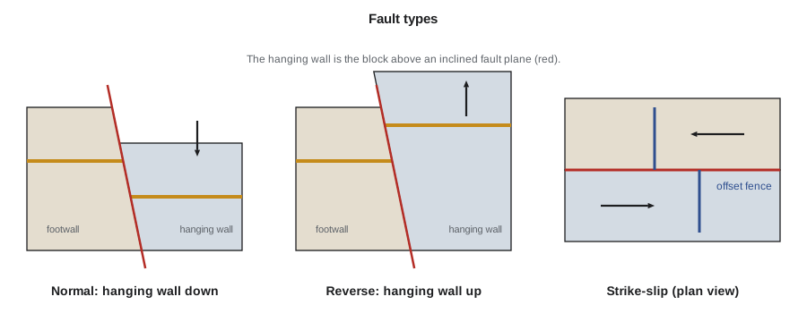
Engineering concerns with faults include the weak, crushed and clay-rich material in fault zones; the contrast in rock type and properties across a fault; groundwater, since faults can act either as conduits or as barriers; and, for active faults, surface rupture and earthquake shaking. A fault is considered active if it has moved in recent geologic time, usually taken as the Holocene, about the last 11,700 years, though definitions differ between agencies and project types. Critical facilities such as dams, nuclear plants and hospitals are not built across active faults, and pipelines and bridges that must cross them are designed to accommodate the expected offset.
Unconformities and contacts
An unconformity is a surface representing a gap in the geologic record, where erosion removed rock or no deposition occurred before younger layers were laid down. An angular unconformity, where tilted older beds are cut off and overlain by flatter younger ones, records a long history of deposition, deformation, uplift and erosion. For engineers, the most common unconformity is the contact between bedrock and the overlying Quaternary deposits: an irregular, eroded surface that may have weathered rock, buried channels, boulders or water-bearing gravel on top of it. Geological contacts of all kinds deserve attention because properties change abruptly across them, and water often flows along them.
Reading a geologic map
A geologic map shows the distribution of rock units at the surface, or beneath a thin cover of soil, with colors and letter symbols keyed to a legend that lists units from youngest at the top to oldest at the bottom. Lines show geological contacts, faults and fold axes, and symbols show measured orientations. Bedrock maps omit the Quaternary cover, while surficial geology maps show the glacial and postglacial deposits; engineers usually need both. Cross-sections drawn along selected lines show the inferred structure at depth.
Several simple rules help interpret map patterns. Horizontal beds outcrop parallel to topographic contours. Vertical beds outcrop as straight lines regardless of topography. Dipping beds make V-shaped patterns where they cross valleys; the rule of Vs states that the V points in the direction of dip, except where the beds dip downstream more gently than the valley floor. On a fold, older rocks are found in the core of an anticline and younger in the core of a syncline. Faults offset contacts and often juxtapose units of different ages.
| Map pattern | Interpretation |
|---|---|
| Contacts follow contour lines | Horizontal beds |
| Contacts cross topography as straight lines | Vertical beds or faults |
| V-shaped contacts in valleys pointing downstream | Beds dip downstream more steeply than the valley gradient |
| Older units in core, symmetric repetition outward | Anticline (or eroded dome) |
| Younger units in core, symmetric repetition outward | Syncline (or basin) |
| Abrupt offset of units along a line | Fault |
Geologic maps for the United States are produced by the US Geological Survey and state surveys such as the Washington Geological Survey, many of them available free online through the National Geologic Map Database and state interactive portals with geology, hazard, lidar and borehole layers. For a site investigation, Kestrel's desk study for the hospital began with the state geologic map, a surficial geology map of the Spokane area, and water well logs, which together suggested about 30 to 40 m of glacial flood gravel and lake silt over basalt.
Finding strike and dip from three boreholes
Where a planar contact, such as the top of a bedrock layer or a distinctive clay seam, is found in three boreholes that do not lie on a straight line, its strike and dip can be found from the three elevations. This is the classic three-point problem. The borehole positions and contact elevations define three points on the plane. On the line joining the highest and lowest points, find the location where the contact has the same elevation as the middle point; the line from there to the middle borehole is a strike line. The dip is the slope measured perpendicular to that line. The same result comes from fitting a plane \(z = a x + b y + c\) through the three points, with the dip angle given by \(\tan\delta = \sqrt{a^2 + b^2}\).
The three-point method assumes the contact is a plane over the area of the boreholes, which is reasonable for a tilted sedimentary bed but not for an eroded bedrock surface or a glacial deposit. Its main use is to predict where a dipping layer will be encountered at a new location, such as a proposed footing or a point along a tunnel, and to check whether a fourth borehole agrees with the prediction. When it does not, the disagreement itself is information: there may be a fold, a fault or a channel between the holes.
Stereonets
For rock slopes and tunnels, orientation data from many joints are plotted on stereographic projections. Each plane is represented by its pole, the point where a line perpendicular to the plane pierces the lower half of a reference sphere. Clusters of poles reveal joint sets, and the mean orientation of each set can be compared with the orientation of a slope face or tunnel to check for plane, wedge and toppling failure, as introduced in lesson 4. Modern software contours pole densities, identifies sets and runs kinematic checks automatically, but the engineer still needs to understand what the plot means.
Common mistakes
MistakeMeasuring dip in a cut face that is not perpendicular to strike and reporting it as the true dip.
InsteadCorrect the apparent dip using the angle between the section and strike.
MistakeUsing only a bedrock map for a site with thick glacial cover.
InsteadConsult surficial geology maps and well records too; the deposits above rock often control design.
MistakeAssuming a borehole intersection length equals the bed thickness.
InsteadMultiply by the cosine of the dip for a vertical hole in a dipping bed.
MistakeTreating all faults as equally hazardous.
InsteadDistinguish active faults (rupture and shaking hazard) from inactive ones (weak zone and water path only).
Summary and key terms
- Strike and dip, or dip direction and dip, describe the orientation of planar features.
- Sections not perpendicular to strike show a smaller apparent dip: \(\tan\alpha = \tan\delta\sin\beta\).
- Anticlines have old rocks in the core and synclines young rocks; fold hinges are often highly fractured.
- Faults are normal, reverse (thrust) or strike-slip; fault zones are weak and may be active.
- Unconformities, especially the rock–soil contact, are irregular surfaces where properties and water conditions change.
- Geologic maps, cross-sections and stereonets turn surface observations into a three-dimensional ground model.
- Strike
- The compass direction of a horizontal line on an inclined plane.
- Dip
- The angle of a plane below the horizontal, measured perpendicular to strike.
- Apparent dip
- The inclination of a plane seen in a section not perpendicular to strike.
- Anticline
- An arch-shaped fold with the oldest rocks in its core.
- Syncline
- A trough-shaped fold with the youngest rocks in its core.
- Normal fault
- A fault in which the hanging wall moves down relative to the footwall.
- Unconformity
- A buried erosion or non-deposition surface representing a gap in the geologic record.
- Active fault
- A fault that has moved in recent geologic time and may move again.
Practice problems
Work each problem on paper first, then reveal the answer to check.
A bed dips 40°. What apparent dip is seen in a section at 30° to strike?
Show answer
\(\tan\alpha = \tan 40^\circ \sin 30^\circ = 0.420\), so \(\alpha = 22.8^\circ\).
A layer dipping 35° outcrops over a width of 10 m on level ground perpendicular to strike. What is its true thickness?
Show answer
\(t = 10 \sin 35^\circ = 5.7\) m.
Which rocks are found in the core of a syncline?
Show answer
The youngest rocks.
In a reverse fault, which block moves up?
Show answer
The hanging wall.
How do horizontal beds appear on a geologic map?
Show answer
Their contacts follow the topographic contour lines.
Why is the bedrock–Quaternary contact important to engineers?
Show answer
It is irregular and often has weathered rock, boulders, buried channels or water-bearing gravel along it.
Lesson quiz · 5 questions
Score 60% or more to complete this lesson.
Create a free account to save your progress, take quizzes and earn a certificate.