
CHE-446 · Lesson 6 of 12 · 21 min
Pumps, compressors, reactors and storage
Lesson 5 sized the static equipment that does the separating and the heat transfer. This lesson covers the rest of the equipment list: the machines that move fluids, the reactor that makes the ester, and the tanks that hold raw materials and product. These items are easy to underestimate. A pump looks cheap on its own, but a plant has many of them, each with a spare, a motor, a starter and piping. Storage tanks look simple, but on a small specialty chemical plant they can be a quarter of the installed cost, and they also hold most of the plant's hazardous inventory. Theo spends a week on this part of the list, and it changes the cost estimate more than he expected.
Pumps
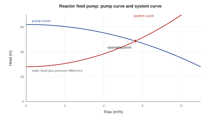
Each pump is specified by its flow, the head it must deliver, the fluid properties and the material. The flow comes from the stream table, with a margin for control; Ingrid's design basis uses 20 %. The head comes from a hydraulic calculation: the difference in pressure between the source and destination, the difference in elevation, the friction losses in the pipe and fittings, and the pressure drop across control valves and instruments. In FEL-3, Theo estimates friction from rough line lengths on the plot plan and allows a fixed drop for each control valve, typically 0.7 to 1 bar, because a control valve needs a share of the system pressure drop to control well.
The power a pump needs is the hydraulic power divided by its efficiency. Hydraulic power is the volumetric flow times the pressure rise, or \(\rho g Q H\) in terms of head. Small centrifugal pumps are not very efficient, often 40 to 60 %, because the losses in a small impeller and casing are a larger share of the work. The motor is then chosen from the next standard size above the shaft power, with an allowance for running at the end of the pump curve.
# Pumps, a compressor, the pre-reactor and storage for the ester line (illustrative)
import math
g, rho = 9.81, 900.0
pumps = [("P-401 reactor feed", 5.1, 45, 0.55), ("P-402 reflux", 6.0, 30, 0.50),
         ("P-403 product to storage", 2.6, 35, 0.45), ("P-404 wastewater", 0.7, 25, 0.40)]
print("pump                      flow m3/h  head m   efficiency   shaft kW   motor kW")
tot = 0
for n, q, h, eta in pumps:
    P = rho * g * h * q / 3600 / eta / 1000
    motor = max(1.5, math.ceil(P / 0.9 * 1.15 * 2) / 2)    # 15 % margin, round up to 0.5 kW steps
    tot += motor
    print(f"  {n:24s} {q:6.1f}   {h:5.0f}     {eta:.2f}        {P:5.2f}      {motor:4.1f}")
print(f"installed pump motors {tot:.1f} kW")
# Mechanical vapor recompression option on the ester column (CHE-350): isentropic estimate
k, T1, P1, P2, m_kg_s, cp = 1.10, 345.0, 101.0, 337.0, 0.80, 1.40   # vapor, kJ/(kg K)
Ws = m_kg_s * cp * T1 * ((P2 / P1) ** ((k - 1) / k) - 1)
print(f"\nMVR compressor: isentropic {Ws:.0f} kW, shaft at 75 % {Ws/0.75:.0f} kW")
# Pre-reactor check against CHE-345: volume = design factor x ideal
V_ideal = 2.08; V = V_ideal * 1.10 * 1.25
print(f"pre-reactor volume {V:.2f} m3 (ideal {V_ideal} x 1.10 catalyst aging x 1.25 margin)")
# Storage: days of cover at design rate
store = [("ethyl acetate product", 2.30, 0.90, 14), ("glacial acetic acid", 1.585, 1.05, 21), ("ethanol feed day tank", 1.211, 0.79, 2)]
print("\ntank                    t/h   density  days   working m3   nominal m3 (at 85 % fill)")
for n, r, d, days in store:
w = r * 24 * days / d; print(f" {n:22s} {r:5.2f} {d:5.2f} {days:3d} {w:8.0f} {w/0.85:8.0f}")pump flow m3/h head m efficiency shaft kW motor kW P-401 reactor feed 5.1 45 0.55 1.02 1.5 P-402 reflux 6.0 30 0.50 0.88 1.5 P-403 product to storage 2.6 35 0.45 0.50 1.5 P-404 wastewater 0.7 25 0.40 0.11 1.5 installed pump motors 6.0 kW MVR compressor: isentropic 45 kW, shaft at 75 % 60 kW pre-reactor volume 2.86 m3 (ideal 2.08 x 1.10 catalyst aging x 1.25 margin) tank t/h density days working m3 nominal m3 (at 85 % fill) ethyl acetate product 2.30 0.90 14 859 1010 glacial acetic acid 1.58 1.05 21 761 895 ethanol feed day tank 1.21 0.79 2 74 87
The four main pumps of the ester line are all small. The reactor feed pump, the largest, moves about 5 m³/h against 45 m of head and needs about 1 kW at the shaft; every pump gets a 1.5 kW motor, the smallest standard size the site uses for process pumps. The total installed motor power for these four is 6 kW, and with spares installed alongside, eight pumps appear in the equipment list. The power cost is trivial against the steam bill, which is the lesson Malik draws: on a plant like this, the energy question is steam, not electricity, and the place to look for savings is the column reboilers, not the pumps.
Pump type matters more than size here. Centrifugal pumps are standard for clean liquids at these flows. For the acid service, the team specifies sealless magnetic drive pumps, because a mechanical seal on hot acetic acid is a common source of leaks, and a leak of hot acid near operators is a hazard. Sealless pumps cost more and cannot run dry, so the design adds low-flow protection. Dev asks for a sample point after each product pump so that the laboratory can check product quality at the tank inlet rather than only in the tank.
Compressors
The ester line as drawn in lesson 3 has no large compressor, but one of the options the team is weighing does. Lesson 4 showed that the plant cannot recover much heat by exchange, because the reboilers and condensers sit at similar temperatures. Mechanical vapor recompression, or MVR, gets around this by compressing the overhead vapor of a column so that it condenses at a higher temperature, high enough to drive the column's own reboiler. The work of compression replaces most of the steam. Theo sizes the MVR compressor for the ester column: compressing the overhead vapor from about 101 to 337 kPa needs about 45 kW of isentropic work, and at an efficiency of 75 % about 60 kW at the shaft.
Sixty kilowatts of electricity to replace close to a megawatt of steam looks like an excellent trade, and in energy terms it is. The cost is capital: an MVR compressor, its motor and drive, its controls and the larger reboiler it needs come to about 1.6 million US dollars in Lucia's estimate, and a compressor also adds maintenance and a new failure mode. Whether it pays depends on the price of steam against the price of electricity, which is the question lesson 12 takes up. For now, it goes on the equipment list as an option, with its own line in the estimate.
Worked problem
Compressor power
About 0.80 kg/s of overhead vapor at 345 K is compressed from 101 to 337 kPa. Take \(c_p = 1.40\) kJ/(kg K) and \(\gamma = 1.10\). Estimate the isentropic work and the shaft power at 75 % efficiency.
Show solution
- For an ideal gas, \(W_s = \dot m\, c_p\, T_1 [(p_2/p_1)^{(\gamma-1)/\gamma} - 1]\).
- \((\gamma-1)/\gamma = 0.0909\); \((337/101)^{0.0909} = 3.34^{0.0909} = 1.116\).
- \(W_s = 0.80 \times 1.40 \times 345 \times 0.116 = 45\) kW.
- Shaft power \(= 45 / 0.75 = 60\) kW.
Answer: About 60 kW at the shaft, small against the nearly 1 MW of latent heat the vapor carries.
The example matches the code. The isentropic work rises with the inlet temperature and with the pressure ratio, so the designer keeps the ratio as small as the reboiler temperature difference allows. A ratio of about three, as here, is at the upper end of what a single-stage MVR machine handles on a distillation column; larger lifts need two stages or a different heat pump.
Reactors
The pre-reactor was designed in CHE-345, and Theo now carries its size into the equipment list with the margins it needs. The kinetic design gave an ideal catalyst volume of about 2.1 m³ to reach the target conversion. Ion-exchange resin catalysts lose activity over months of service, so the design allows for an end-of-run activity about 10 % lower. Then a design margin of 25 % covers uncertainty in the kinetics, which were measured in a laboratory and not yet in a pilot plant. The result is about 2.9 m³ of bed. The bed is held in a vertical stainless vessel about 1.1 m in diameter, with screens to hold the resin, a distributor at the top, and connections to change out the catalyst.
Reactor design in FEL-3 is not only about volume. The team must decide how the catalyst is loaded and changed, how the vessel is protected from overpressure if a feed valve fails open, and how temperature is controlled. The reaction is only mildly exothermic, so the pre-reactor runs nearly adiabatically with a small temperature rise, and the main hazard is not runaway but the flammable inventory. The reactive column, which does most of the conversion, was sized in lesson 5 as a column; its catalytic packing is a licensed item, priced from the vendor's quote.
Storage tanks
Storage is sized from days of supply rather than minutes of hold-up. The product tanks must hold enough ester to cover the time between shipments plus a margin for a late truck or railcar; the raw material tanks must cover the time between deliveries plus a margin for supply disruption. Each choice is a trade-off between the cost of the tank, the cost of the working capital tied up in its contents, and the cost of running out. Each tank is also an inventory of flammable liquid, and lesson 11 will return to that.
The first draft, which Theo prepared from the CHE-390 market study, assumed 14 days of product storage, 21 days of acid storage and a two-day ethanol day tank fed from the existing ethanol plant. The code turns those into volumes. The product needs about 860 m³ of working volume, which at an 85 % fill limit means about 1,010 m³ of nominal tank capacity. The acid needs about 760 m³ working and about 900 m³ nominal, and the ethanol day tank about 75 m³. Tanks are bought in standard sizes, and the first estimate allows three 1,000 m³ tanks, two for product and one for acid, plus smaller tanks for ethanol and off-specification material.
| Tank | Basis | Working volume | Nominal at 85 % fill |
|---|---|---|---|
| Ethyl acetate product | 14 days at 2.30 t/h | 859 m³ | 1,010 m³ |
| Glacial acetic acid | 21 days at 1.58 t/h | 761 m³ | 895 m³ |
| Ethanol day tank | 2 days at 1.21 t/h | 74 m³ | 87 m³ |
| Off-specification | About 2 days of product | About 110 m³ | About 130 m³ |
The tanks have their own design questions. Ethyl acetate and ethanol are flammable liquids with flash points below room temperature, so their tanks need nitrogen blanketing or internal floating roofs to keep the vapor space out of the flammable range and to control emissions, and they sit inside a dike that can hold the contents of the largest tank. Glacial acetic acid freezes at about 17 °C, so in an Iowa winter its tank and lines need heating and insulation. Product tanks need sampling and, for a solvent sold to coatings and pharmaceutical customers, cleanliness: Dev asks for stainless steel tanks, which settles another line of the estimate.
When Lucia prices the first draft, the storage tanks and their dikes, foundations, blanketing and heaters come to about a fifth of the installed cost of the whole line. Carla, who will run the plant, asks whether 14 days of product is really needed. Most customers buy by truck, a few by railcar, and the plant ships nearly every day. The question goes on the list for lesson 11, where a smaller inventory turns out to be both cheaper and safer.
Common mistakes
MistakeSizing pumps from flow only.
InsteadHead, including control valve drop, sets the power and the pump type.
MistakeTreating electricity as the main energy cost.
InsteadOn this line, steam dominates; pump power is a few kilowatts.
MistakeUsing the ideal catalyst volume.
InsteadAllow for activity loss over the run and for kinetic uncertainty.
MistakeSizing storage from habit.
InsteadDays of storage should come from shipping patterns, supply risk and working capital.
MistakeForgetting that glacial acetic acid freezes at about 17 °C.
InsteadHeated, insulated tanks and lines are needed in winter.
Summary and key terms
- Pump power is \(\rho g Q H / \eta\); the four main pumps need about 6 kW of installed motors.
- Sealless pumps are specified for hot acid to avoid seal leaks.
- An MVR compressor of about 60 kW could replace most of the ester column's steam at a capital cost of about 1.6 million.
- The pre-reactor bed is about 2.9 m³ after allowances for catalyst aging and kinetic uncertainty.
- Storage sized at 14 to 21 days needs about 1,000 m³ tanks and is a large share of cost and inventory.
- Head
- The energy per unit weight a pump adds to a liquid, expressed as a height of liquid.
- System curve
- The head the piping system requires at each flow.
- Mechanical vapor recompression
- Compressing column overhead vapor so it can heat the same column's reboiler.
- Isentropic efficiency
- The ratio of ideal reversible compression work to actual work.
- Working volume
- The tank volume between the low and high operating levels.
- Nitrogen blanketing
- Filling a tank vapor space with nitrogen to keep it out of the flammable range.
Practice problems
Work each problem on paper first, then reveal the answer to check.
What shaft power does a pump need for 5.1 m³/h at 45 m head and 55 % efficiency, with density 900 kg/m³?
Show answer
About 1.0 kW.
Why does a control valve need a share of the pressure drop?
Show answer
Without enough drop it cannot change the flow much as it opens and closes.
What is the main trade-off with MVR?
Show answer
Lower steam cost against higher capital, maintenance and electricity.
Why is the catalyst bed larger than the ideal volume?
Show answer
Allowances for activity loss and kinetic uncertainty.
What fill limit was used to turn working volume into nominal volume?
Show answer
85 %.
Why is the acetic acid tank heated?
Show answer
Glacial acetic acid freezes at about 17 °C.
Lesson quiz · 5 questions
Score 60% or more to complete this lesson.
Create a free account to save your progress, take quizzes and earn a certificate.