
CHE-374 · Lesson 11 of 12 · 23 min
Safety instrumented systems and alarm management
Every control loop Theo has tuned so far assumes that its instruments work. Some day one will not. A transmitter will freeze at a normal value, a valve will stick open, a controller card will fail, or an operator will set the wrong set point. When that happens on a loop that guards a hazard, the plant needs a second line of defense that does not share the failure. This lesson covers the two parts of that defense that belong to control engineers: safety instrumented systems, which act automatically, and alarms, which ask a person to act. Both are governed by process safety management under OSHA's Process Safety Management standard, 29 CFR 1910.119, together with EPA's Risk Management Program rule where a listed chemical exceeds its threshold quantity, and both are judged by how reliably they work on the one day they are needed.
Layers of protection
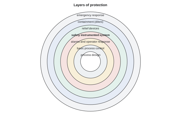
Process safety is built in layers, often drawn as the skins of an onion around the process. At the center is inherently safer design: less hazardous material, lower pressures, smaller inventories. Around it is the basic process control system, the DCS loops of the earlier lessons. Next come alarms with operator response. Then the safety instrumented system, SIS, which measures, decides and acts independently of the control system. Then physical protection such as relief valves and rupture discs, then containment such as dikes, and finally plant and community emergency response. Each layer catches some of the events that get past the one inside it. The aim is not for any one layer to be perfect, but for the combination to make a serious accident rare enough to be tolerable.
Safety instrumented functions and SIL
A safety instrumented function, SIF, is one protective action: a sensor, a logic solver and a final element that together bring the process to a safe state when a dangerous condition is detected. An example is a high temperature in the pre-reactor feed heater closing a dedicated steam block valve. The design, installation, testing and management of SIFs follow IEC 61511, adopted in Canada as CAN/CSA-C22.2 No. 61511-1 and in the US as ANSI/ISA-61511-1-2018; the adoptions follow the international text closely. The procedures at Kingfisher Bioenergy cite ISA-61511, and the standard's requirements are written into the plant's process safety procedures.
Each SIF has a target safety integrity level, SIL, set by the risk reduction it must deliver. For functions that are demanded rarely, the measure is the average probability of failure on demand, PFDavg: the chance that the function will not work when the dangerous condition arises.
| SIL | PFDavg | Risk reduction factor |
|---|---|---|
| 1 | 0.1 to 0.01 | 10 to 100 |
| 2 | 0.01 to 0.001 | 100 to 1,000 |
| 3 | 0.001 to 0.0001 | 1,000 to 10,000 |
| 4 | 0.0001 to 0.00001 | 10,000 to 100,000 |
In the process industries most SIFs are SIL 1 or SIL 2; SIL 3 is uncommon and usually prompts a search for an inherently safer design, and SIL 4 is avoided.
Layer of protection analysis
How much protection a hazard needs is commonly decided by layer of protection analysis, LOPA, a semi-quantitative method that follows a hazard and operability study. Theo's first LOPA concerns the ester pre-reactor of CHE-345. Its resin catalyst must stay below about 120 °C. If the feed heater's temperature controller fails high, the hot feed degrades the resin and raises the bed temperature and pressure, and ester vapor could be released through the relief valve into an area where it might ignite. The team works through the scenario with numbers taken from the company's LOPA guidelines, which, like most such tables, are order-of-magnitude values.
# Layer of protection analysis for the pre-reactor feed heater, a SIF check, and alarm rate statistics
import random
target = 1e-5                     # tolerable frequency of a fire with serious injury, per year (company criterion, illustrative)
init = 0.1                        # heater temperature control loop fails high, per year
ipl = (("relief valve sized for the fire and vapor case", 0.01),)
cm = (("probability of ignition", 0.3), ("probability someone is present", 0.5))
f = init
for name, p in ipl + cm: f *= p
print(f"without the high-temperature alarm (it shares the loop's transmitter, so it is not independent): {f:.1e} per year")
pfd_req = target / f; print(f"required PFD of a new safety function: <= {pfd_req:.3f}  (risk reduction >= {1 / pfd_req:.0f}) -> SIL {1 if pfd_req >= 0.01 else 2}")
lam = (("temperature transmitter", 5e-7), ("safety logic solver", 1e-7), ("steam block valve and solenoid", 2e-6))   # dangerous undetected failures per hour (illustrative)
for TI in (8760.0, 2 * 8760.0):
    pfd = sum(l for n, l in lam) * TI / 2
    print(f"proof test every {TI / 8760:.0f} year(s): PFDavg {pfd:.4f}, RRF {1 / pfd:.0f} -> {'meets' if pfd <= pfd_req else 'misses'} the requirement")
pfd_valves_1oo2 = (5e-7 + 1e-7) * 2 * 8760 / 2 + (2e-6 * 2 * 8760) ** 2 / 3
print(f"with two block valves in series (1oo2) and a 2-year test: PFDavg {pfd_valves_1oo2:.4f}")
# Alarm statistics from a week of (synthetic) alarm-journal counts per 10-minute interval
random.seed(18)
counts = []
for i in range(7 * 144):
    c = sum(1 for _ in range(6) if random.random() < 0.12)
    if 300 <= i < 309: c += random.randint(12, 25)     # a feed pump trip: an alarm flood
    counts.append(c)
total = sum(counts); hours = len(counts) / 6
floods = [i for i, c in enumerate(counts) if c > 10]
print(f"week: {total} alarms, average {total / hours:.1f} per hour ({total / len(counts):.2f} per 10 min)")
print(f"intervals with more than 10 alarms: {len(floods)} ({100 * len(floods) / len(counts):.1f} % of the time); peak {max(counts)} in 10 min")
top = sorted(counts[300:309], reverse=True)[:3]
print(f"flood alarms: {sum(counts[300:309])} in 90 minutes; the busiest intervals carried {top}")without the high-temperature alarm (it shares the loop's transmitter, so it is not independent): 1.5e-04 per year required PFD of a new safety function: <= 0.067 (risk reduction >= 15) -> SIL 1 proof test every 1 year(s): PFDavg 0.0114, RRF 88 -> meets the requirement proof test every 2 year(s): PFDavg 0.0228, RRF 44 -> meets the requirement with two block valves in series (1oo2) and a 2-year test: PFDavg 0.0057 week: 901 alarms, average 5.4 per hour (0.89 per 10 min) intervals with more than 10 alarms: 9 (0.9 % of the time); peak 26 in 10 min flood alarms: 188 in 90 minutes; the busiest intervals carried [26, 24, 23]
The initiating event, failure of the temperature loop, is taken at 0.1 per year. The relief valve, sized for this case, is an independent protection layer with a PFD of 0.01. The probability of ignition is taken as 0.3 and of someone being present as 0.5. The plant already has a high-temperature alarm, but it uses the same transmitter as the control loop, so if the transmitter fails the alarm fails with it; it is not independent and cannot be credited. The mitigated frequency is \(0.1 \times 0.01 \times 0.3 \times 0.5 = 1.5 \times 10^{-4}\) per year, against the company's tolerable frequency for this consequence of \(10^{-5}\) per year. A new SIF is needed with a PFD no greater than \(10^{-5}/1.5 \times 10^{-4} = 0.067\): a risk reduction of at least 15, which is SIL 1.
Worked problem
Is a SIF needed?
An initiating event occurs 0.2 times a year. Credited layers are an independent alarm with operator response, PFD 0.1, and a relief valve, PFD 0.01. The target is \(10^{-4}\) per year. Is a SIF needed?
Show solution
- Mitigated frequency: \(0.2 \times 0.1 \times 0.01 = 2 \times 10^{-4}\) per year.
- Required extra reduction: \(2 \times 10^{-4}/10^{-4} = 2\).
Answer: Yes: an extra layer with PFD at most 0.5 is needed. A SIF would be at least SIL 1; another non-instrumented layer might suffice.
Designing the SIF to meet its target
The proposed SIF uses its own temperature transmitter in a separate thermowell, a certified safety logic solver, and a dedicated steam block valve with its own solenoid, separate from the control valve. Its PFDavg is estimated from the dangerous undetected failure rate, \(\lambda_{DU}\), of each element and the proof test interval \(T_I\). For a single element tested periodically, \(PFD_{avg} \approx \lambda_{DU}T_I/2\). Taking illustrative rates of \(5 \times 10^{-7}\) per hour for the transmitter, \(10^{-7}\) for the logic solver and \(2 \times 10^{-6}\) for the valve and solenoid, a yearly proof test gives a PFDavg of 0.011, a risk reduction of 88, comfortably inside SIL 1 and better than the required 0.067. With a two-year test interval it rises to 0.023, still adequate. The valve dominates, as final elements usually do. Adding a second block valve in series, voted one-out-of-two, brings the two-year figure down to 0.006. These estimates assume tests that actually find the failures, which is why proof test procedures are written in detail and their results recorded.
Independence is the theme throughout. The SIF must not share sensors, logic or valves with the control loop that might cause the demand. Its trip setting must leave time for the process to be stopped before the hazard develops, accounting for sensor lag and valve stroke time. Bypasses for maintenance must be controlled and logged. Any change to the function, even a trip setting, goes through management of change.
Alarms and their purpose
An alarm is a signal to an operator that a response is required. That definition, from ANSI/ISA-18.2 and its international counterpart IEC 62682, rules out much of what many plants alarm. A message that a pump has started, or a value that crossed a limit but needs no action, is not an alarm. Every alarm should have a defined cause, a defined operator response and enough time for that response to work. When too many alarms sound, operators cannot respond to the important ones; investigations of several major accidents found operators facing hundreds of alarms in the minutes before an explosion.
Alarm management follows a life cycle: an alarm philosophy document sets the rules; rationalization reviews each alarm against them, assigning a priority and recording its cause, consequence and response; design implements the alarms with suitable deadbands and delays; and monitoring measures performance and drives improvement. Commonly cited targets, drawn from ISA-18.2 and the earlier EEMUA 191 guidance, are an average of about one alarm per ten minutes per operator, or roughly six per hour, as very likely acceptable, with up to about two per ten minutes manageable; alarm floods, often defined as more than ten alarms in ten minutes, should occur less than about 1 % of the time.
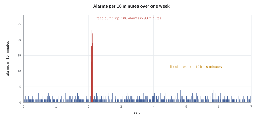
Theo analyses a week of the ester unit's alarm journal. It contains 901 alarms, an average of 5.4 per hour, within the target. But nine 10-minute intervals had more than ten alarms, 0.9 % of the time, nearly all during a single feed pump trip, when 188 alarms arrived in 90 minutes and one interval carried 26. In those minutes the operator could not have read them all, let alone acted on them. Theo's analysis finds that most of the flood alarms were consequences of the trip, low flows, levels and temperatures downstream, rather than independent problems.
Worked problem
Alarm rate check
An operator position receives 1,450 alarms in a 7-day week. What is the average rate per 10 minutes, and how does it compare with the target?
Show solution
- There are \(7 \times 24 \times 6 = 1{,}008\) intervals of 10 minutes.
- Rate: \(1{,}450/1{,}008 = 1.44\) per 10 minutes, about 8.6 per hour.
Answer: Above the 1 per 10 minutes target and close to the manageable limit; a rationalization effort is warranted.
Fixing the flood
The cures for floods are well established. State-based alarming suppresses alarms that are expected in a known state: when the feed pump trips and the unit goes to its trip state, the downstream low-flow and low-level alarms are suppressed automatically, and the operator sees the trip alarm and its first-out cause. Chattering alarms, which repeat many times as a noisy signal crosses a limit, are cured with deadbands and on-delay timers. Duplicate alarms on the same measurement are removed. Alarm priorities are set from the severity of the consequence and the time available to respond, so that the high-priority list stays short. Theo proposes state-based suppression for the feed pump trip; the rationalization team accepts it, together with deadband changes on eleven chattering level alarms, and the change goes through management of change before implementation.
Malik reminds him of one boundary. An alarm with operator response can be credited as a protection layer in LOPA only if it is independent of the initiating cause, the operator has enough time to act, the response is trained and practiced, and the alarm is managed under the philosophy. The high-temperature alarm on the feed heater failed the first test. Alarms and SIS are complementary: alarms rely on people with time to think; SIFs act in seconds without anyone.
Common mistakes
MistakeCrediting an alarm that shares a sensor with the failing control loop.
InsteadProtection layers must be independent of the initiating event.
MistakeAssuming a SIF meets its SIL without proof testing.
InsteadPFDavg depends on tests that actually reveal dangerous failures.
MistakeAlarming every limit crossing.
InsteadAn alarm must require a defined operator response.
MistakeTreating an alarm flood as an operator problem.
InsteadFloods are a design problem; use state-based suppression and rationalization.
Summary and key terms
- Protection is layered: design, control, alarms, SIS, relief, containment and emergency response.
- SIFs follow IEC 61511; SIL 1 needs a PFDavg between 0.1 and 0.01.
- LOPA showed the feed heater needs a SIF with PFD at most 0.067, which is SIL 1.
- With yearly proof tests the proposed SIF reaches PFDavg 0.011; the valve dominates.
- The alarm journal averaged 5.4 alarms per hour, but a pump trip caused a flood of 188 alarms in 90 minutes.
- Safety instrumented system
- An independent system of sensors, logic and final elements that brings a process to a safe state.
- Safety instrumented function
- One protective action performed by a safety instrumented system.
- Safety integrity level
- A band of required risk reduction for a safety instrumented function.
- PFDavg
- The average probability that a function fails to act when demanded.
- Layer of protection analysis
- A semi-quantitative method for deciding whether existing protection is enough.
- Alarm flood
- A period when alarms arrive faster than an operator can respond, often more than 10 in 10 minutes.
- Rationalization
- A systematic review of each alarm against the alarm philosophy.
Practice problems
Work each problem on paper first, then reveal the answer to check.
A SIF needs a risk reduction of 250. What SIL is that?
Show answer
SIL 2.
Estimate PFDavg for \(\lambda_{DU} = 10^{-6}\) per hour and a 1-year test interval.
Show answer
\(10^{-6} \times 8760/2 = 0.0044\).
Why does the final element usually dominate a SIF's PFD?
Show answer
Valves have the highest dangerous undetected failure rates.
Give one condition for crediting an alarm in LOPA.
Show answer
Independence from the initiating event, or adequate time to respond, or trained response.
An alarm repeats 40 times an hour as a level hovers at its limit. Suggest a fix.
Show answer
Add a deadband or an on-delay.
What does state-based alarming do after a pump trip?
Show answer
Suppresses expected consequential alarms so the operator sees the cause.
Lesson quiz · 5 questions
Score 60% or more to complete this lesson.
Create a free account to save your progress, take quizzes and earn a certificate.