
CHE-312 · Lesson 12 of 12 · 33 min
Heat exchangers: analysis, design and the capstone
Every lesson so far comes together in a heat exchanger. Conduction through a tube wall, convection on each side, fins on a gas side, boiling or condensation in many process units, and fouling that slowly adds resistance: all appear in one device whose job is to move heat from one fluid to another. Northgate's expansion needs three: a plate heat exchanger in the new substation at Riverside General Hospital, a condensing economizer on the boiler stacks, and, for one of the industrial customers on the network, a process cooler. This lesson presents the two standard analysis methods, the log-mean temperature difference and effectiveness-NTU, shows how fouling and pressure drop shape a design, and closes with the capstone review of the whole expansion.
Types of heat exchangers
Heat exchangers are classified by flow arrangement and construction. In a parallel-flow exchanger both fluids enter at the same end and flow in the same direction; in a counterflow exchanger they flow in opposite directions; in a crossflow exchanger they flow at right angles, with either fluid mixed or unmixed across the flow. Shell-and-tube exchangers, the workhorses of the process industries, place a bundle of tubes inside a cylindrical shell, with baffles that direct the shell-side fluid across the tubes; the tube-side fluid may make one, two or more passes. Their construction and mechanical design follow the standards of the Tubular Exchanger Manufacturers Association (TEMA) and the pressure-vessel codes. Plate heat exchangers stack corrugated metal plates with gaskets or brazed joints, forming thin channels in which the corrugations create strong turbulence even at modest velocities; they are compact, efficient and easy to expand, and they dominate district energy substations. Finned-tube exchangers, such as economizers, air coolers and building coils, add extended surface to a gas side.
The overall heat transfer coefficient and fouling
For a tubular exchanger, the resistances of Lesson 2 add in series: inside convection, inside fouling, the tube wall, outside fouling and outside convection. Based on the outside area,
where the overall surface efficiency \(\eta_o\) appears if the outside is finned. Fouling is the accumulation of deposits: scale from hard water, corrosion products, biological growth in cooling water, coke and polymers in hydrocarbon streams, soot and ash on gas sides. Its resistance grows over time and is allowed for in design by fouling factors, typically \(10^{-4}\) to \(10^{-3}\) m²·K/W, taken from TEMA tables or company practice. Fouling allowances can raise the required area by 20 to 60 percent or more, so they are among the most consequential numbers in a design. Too small an allowance gives an exchanger that fails early; too large gives an oversized exchanger whose excess area runs with low velocities, which can itself promote fouling. Plate exchangers, with their high turbulence and clean channels, use much smaller allowances than shell-and-tube units.
The log-mean temperature difference method
Applying the energy balance and the rate equation to a small element of a counterflow or parallel-flow exchanger, and integrating over the length, gives
where \(\Delta T_1\) and \(\Delta T_2\) are the temperature differences between the two fluids at the two ends. For counterflow, \(\Delta T_1 = T_{h,i} - T_{c,o}\) and \(\Delta T_2 = T_{h,o} - T_{c,i}\); for parallel flow, \(\Delta T_1 = T_{h,i} - T_{c,i}\) and \(\Delta T_2 = T_{h,o} - T_{c,o}\). For the same inlet and outlet temperatures, counterflow always gives the larger log-mean difference and so needs the smaller area. Counterflow also allows the cold fluid to leave hotter than the hot fluid leaves, which parallel flow can never do.
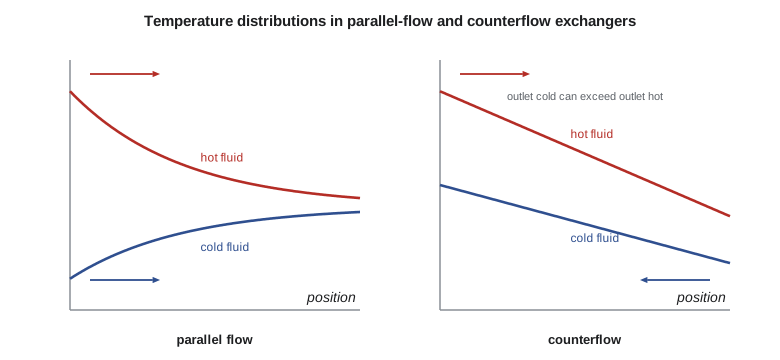
For multipass and crossflow exchangers, the log-mean difference is calculated as if for counterflow and multiplied by a correction factor \(F\), so that \(q = UAF\,\Delta T_{\text{lm,cf}}\). The factor depends on two ratios, \(P = (t_o - t_i)/(T_i - t_i)\) and \(R = (T_i - T_o)/(t_o - t_i)\), and is given by charts or formulas for each configuration. It equals 1 when either fluid changes temperature negligibly, as in a condenser or boiler. Designers generally avoid configurations with \(F\) below about 0.75 to 0.8, because the factor then falls steeply with small changes in conditions, and use more shells in series instead.
The effectiveness-NTU method
The LMTD method is direct when all four terminal temperatures are known and the area is wanted, the sizing problem. When the exchanger is given and the outlet temperatures are wanted, the rating problem, it requires iteration. The effectiveness-NTU method handles both directly. The effectiveness is the ratio of the actual heat rate to the maximum possible, which would occur in an infinitely long counterflow exchanger in which the fluid with the smaller heat capacity rate, \(C_{\min} = (\dot m c_p)_{\min}\), undergoes the largest possible temperature change:
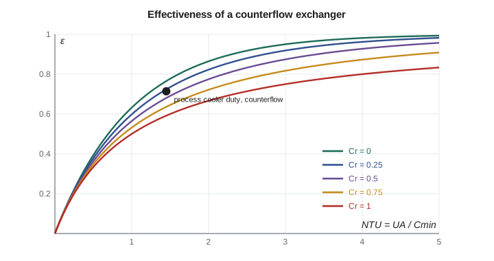
For each flow arrangement, \(\varepsilon\) is a function of NTU and \(C_r\). For counterflow, \(\varepsilon = [1 - e^{-\text{NTU}(1 - C_r)}]/[1 - C_re^{-\text{NTU}(1 - C_r)}]\), which becomes \(\text{NTU}/(1 + \text{NTU})\) when \(C_r = 1\). For parallel flow, \(\varepsilon = [1 - e^{-\text{NTU}(1 + C_r)}]/(1 + C_r)\), which can never exceed \(1/(1 + C_r)\). Formulas for shell-and-tube and crossflow arrangements are in every heat transfer text. When \(C_r = 0\), as for a condensing or boiling fluid whose temperature does not change, every arrangement gives \(\varepsilon = 1 - e^{-\text{NTU}}\). The NTU, a dimensionless size, shows quickly where returns diminish: above an NTU of about 3, more area buys little more heat.
# Heat exchangers: overall coefficient with fouling, LMTD with F, effectiveness-NTU, and the capstone sizing
import math
def lmtd(d1, d2): return (d1 - d2) / math.log(d1 / d2) if abs(d1 - d2) > 1e-9 else d1
def eps_counter(N, Cr):
    return N / (1 + N) if abs(Cr - 1) < 1e-9 else (1 - math.exp(-N*(1-Cr))) / (1 - Cr*math.exp(-N*(1-Cr)))
def eps_parallel(N, Cr): return (1 - math.exp(-N*(1+Cr))) / (1 + Cr)
def eps_shell12(N, Cr):
    s = math.sqrt(1 + Cr**2); e = math.exp(-N * s)
    return 2 / (1 + Cr + s * (1 + e) / (1 - e))
def eps_cross_unmixed(N, Cr): return 1 - math.exp((1/Cr) * N**0.22 * (math.exp(-Cr * N**0.78) - 1))
def ntu_for(eps_target, f, Cr):
    lo, hi = 1e-6, 50.0
    for _ in range(200):
        m = (lo + hi) / 2
        lo, hi = (m, hi) if f(m, Cr) < eps_target else (lo, m)
    return (lo + hi) / 2
def F_12(Thi, Tho, Tci, Tco):                                 # LMTD correction, one shell pass, two or more tube passes
    R, P = (Thi - Tho) / (Tco - Tci), (Tco - Tci) / (Thi - Tci)
    s = math.sqrt(R**2 + 1)
    return s / (R - 1) * math.log((1 - P) / (1 - P*R)) / math.log((2 - P*(R + 1 - s)) / (2 - P*(R + 1 + s)))

# 1. Overall coefficient of a 19 mm OD, 16 mm ID steel tube, clean and fouled (based on outside area)
Do, Di, kw, hi, ho = 0.019, 0.016, 45.0, 4000.0, 1500.0
Rfi, Rfo = 0.000176, 0.000352                                # treated cooling water inside, light organic liquid outside
def Uo(foul):
    return 1 / (Do/(Di*hi) + (Do/Di*Rfi + Rfo if foul else 0) + Do*math.log(Do/Di)/(2*kw) + 1/ho)
print(f"tube U_o: clean {Uo(False):.0f} W/m2.K, fouled {Uo(True):.0f} W/m2.K (design margin {Uo(False)/Uo(True)-1:.0%})")

# 2. Process cooler: 12 kg/s of a light hydrocarbon (cp 2.30 kJ/kg.K) from 95 C to 45 C with cooling water 25 to 40 C
mh, cph, Thi, Tho, Tci, Tco = 12.0, 2300.0, 95.0, 45.0, 25.0, 40.0
Q = mh * cph * (Thi - Tho); mc = Q / (4180 * (Tco - Tci))
dTlm = lmtd(Thi - Tco, Tho - Tci); F = F_12(Thi, Tho, Tci, Tco)
A = Q / (Uo(True) * F * dTlm)
print(f"process cooler: Q = {Q/1e6:.2f} MW, water {mc:.1f} kg/s, counterflow LMTD {dTlm:.1f} K, F = {F:.3f}, area {A:.0f} m2 (1-2 shell)")
Ch, Cc = mh * cph, mc * 4180
Cmin, Cmax = min(Ch, Cc), max(Ch, Cc); Cr = Cmin / Cmax
eps_req = Q / (Cmin * (Thi - Tci))
for name, f in (("counterflow", eps_counter), ("1-2 shell and tube", eps_shell12), ("parallel flow", eps_parallel)):
    try:
        N = ntu_for(eps_req, f, Cr)
        ok = abs(f(N, Cr) - eps_req) < 1e-4
        print(f"  {name:18s}: effectiveness {eps_req:.3f} needs NTU = {N:.2f} -> area {N*Cmin/Uo(True):6.0f} m2" if ok else
              f"  {name:18s}: effectiveness {eps_req:.3f} is not reachable (limit {f(50, Cr):.3f})")
    except ZeroDivisionError:
        pass

# 3. Rating: the same 1-2 exchanger once it is clean (U higher), with the same flows and inlets
N_clean = Uo(False) * A / Cmin
e = eps_shell12(N_clean, Cr); Qc = e * Cmin * (Thi - Tci)
print(f"  when clean: NTU {N_clean:.2f}, effectiveness {e:.3f}, duty {Qc/1e6:.2f} MW, hydrocarbon leaves at {Thi - Qc/Ch:.1f} C")

# 4. Capstone: Riverside General Hospital substation plate exchanger, district 110 -> 70 C, building 55 -> 80 C, 2.5 MW
Q = 2.5e6; U_plate, Rf = 5500.0, 0.00004                     # clean plate U and total fouling allowance, m2.K/W
U = 1 / (1 / U_plate + Rf)
dT = lmtd(110 - 80, 70 - 55)
A = Q / (U * dT)
m_p, m_s = Q / (4210 * 40), Q / (4190 * 25)
print(f"\nsubstation: LMTD {dT:.1f} K, U {U:.0f} W/m2.K, area {A:.1f} m2; district flow {m_p:.1f} kg/s, building flow {m_s:.1f} kg/s")
# part load: the building needs only 55 -> 70 C at the same building flow; what district return temperature results?
C_p_full, C_s = m_p * 4210, m_s * 4190
for frac in (1.0, 0.6, 0.4):
    Cp = C_p_full * frac                                     # district flow throttled by the control valve
    Cmin, Cmax = min(Cp, C_s), max(Cp, C_s); N = U * A / Cmin
    e = eps_counter(N, Cmin / Cmax); Qp = e * Cmin * (110 - 55)
    print(f"  district flow at {frac:.0%}: duty {Qp/1e6:.2f} MW, district return {110 - Qp/Cp:5.1f} C, building supply {55 + Qp/C_s:5.1f} C")

# 5. Condensing economizer, sensible part only: flue gas 165 C cooled by 45 C return water (crossflow, both unmixed)
mg, cpg, mw = 3.0, 1080.0, 8.0
Cg, Cw = mg * cpg, mw * 4190; Cr = Cg / Cw
for UA in (3000.0, 6000.0, 12000.0):
    N = UA / Cg; e = eps_cross_unmixed(N, Cr); q = e * Cg * (165 - 45)
print(f"economizer UA {UA:6.0f} W/K: NTU {N:.2f}, effectiveness {e:.3f}, recovers {q/1000:4.0f} kW, gas leaves at {165 - q/Cg:5.1f} C")tube U_o: clean 1000 W/m2.K, fouled 641 W/m2.K (design margin 56%) process cooler: Q = 1.38 MW, water 22.0 kg/s, counterflow LMTD 34.6 K, F = 0.878, area 71 m2 (1-2 shell) counterflow : effectiveness 0.714 needs NTU = 1.45 -> area 62 m2 1-2 shell and tube: effectiveness 0.714 needs NTU = 1.65 -> area 71 m2 parallel flow : effectiveness 0.714 needs NTU = 2.03 -> area 87 m2 when clean: NTU 2.57, effectiveness 0.801, duty 1.55 MW, hydrocarbon leaves at 38.9 C substation: LMTD 21.6 K, U 4508 W/m2.K, area 25.6 m2; district flow 14.8 kg/s, building flow 23.9 kg/s district flow at 100%: duty 2.50 MW, district return 70.0 C, building supply 80.0 C district flow at 60%: duty 1.86 MW, district return 60.3 C, building supply 73.6 C district flow at 40%: duty 1.34 MW, district return 56.3 C, building supply 68.4 C economizer UA 3000 W/K: NTU 0.93, effectiveness 0.587, recovers 228 kW, gas leaves at 94.5 C economizer UA 6000 W/K: NTU 1.85, effectiveness 0.820, recovers 319 kW, gas leaves at 66.6 C economizer UA 12000 W/K: NTU 3.70, effectiveness 0.961, recovers 374 kW, gas leaves at 49.7 C
Worked problem
A process cooler
An industrial customer cools 12 kg/s of a light hydrocarbon (\(c_p\) = 2.30 kJ/kg·K) from 95 °C to 45 °C with cooling water from 25 °C to 40 °C in a shell-and-tube exchanger with one shell pass and two tube passes. The tubes are 19 mm outside and 16 mm inside diameter, steel, with water inside (\(h_i\) = 4000 W/m²·K, fouling 0.000176 m²·K/W) and hydrocarbon outside (\(h_o\) = 1500 W/m²·K, fouling 0.000352 m²·K/W). Find the duty, the water flow, U, F and the required area, and compare the area with counterflow and parallel-flow arrangements.
Show solution
- \(q = 12(2300)(95 - 45) = 1.38\) MW; water flow \(1.38\times10^6/(4180 \times 15) = 22.0\) kg/s.
- \(U_o\): clean 1000 W/m²·K; with fouling 641 W/m²·K, so fouling adds 56 percent to the required area.
- \(\Delta T_{\text{lm,cf}} = (55 - 20)/\ln(55/20) = 34.6\) K; \(R = 50/15 = 3.33\), \(P = 15/70 = 0.214\), giving \(F = 0.878\).
- \(A = 1.38\times10^6/(641 \times 0.878 \times 34.6) = 71\) m².
- By ε-NTU: \(C_{\min} = 27.6\) kW/K (hydrocarbon), \(C_r = 0.30\), \(\varepsilon = 50/70 = 0.714\). Counterflow needs NTU = 1.45 (62 m²); the 1-2 shell needs 1.65 (71 m²); parallel flow needs 2.03 (87 m²).
Answer: The two methods agree for the shell-and-tube unit, as they must. Counterflow would save 13 percent of the area but is awkward to build with long tubes; the 1-2 shell is the usual compromise. When the exchanger is new and clean, the same 71 m² gives NTU = 2.57 and ε = 0.80: the hydrocarbon would leave at about 39 °C, and the customer's control valve would throttle the water to hold 45 °C. That margin is the fouling allowance, and it is consumed over the run between cleanings.
Design considerations
Thermal sizing is only part of design. Each side has an allowable pressure drop, which limits velocity and therefore the coefficient; a good design uses most of the allowable pressure drop on each side, because higher velocity raises \(h\) and reduces fouling. Which fluid goes in the tubes matters: the more fouling, corrosive or high-pressure fluid usually goes inside, where tubes are easier to clean and the shell need not resist the pressure. Thermal expansion between shell and tubes must be accommodated with floating heads, U-tubes or expansion joints. Materials must resist corrosion, and in condensing flue gas they must resist acid condensate, which rules out ordinary carbon steel and aluminum. Finally, the exchanger must be controllable: an exchanger with far more area than needed can make control unstable at low loads, and one sized with no margin cannot cope with fouling or a hot summer day.
The capstone: Northgate's expansion design review
Elena calls the design review for the expansion. Each member of the team presents one piece, and each piece rests on one or more lessons of this course.
Tomás opens with the existing plant. The bare 12 m of steam main loses 23.4 kW, half of it by radiation, at a fuel cost of roughly 3,200 per year at the assumed gas price, and the damaged outdoor section loses nearly 4 kW per meter on a windy winter night (Lessons 1, 6 and 10). The infrared survey found that the stainless flanges, which looked cold, are near steam temperature. Insulation and jacket repairs are approved immediately; they pay back in under a year.
Kofi presents the transmission main. The pre-insulated DN200 pipe loses about 43 W/m in the tunnel and 49 W/m buried, with the foam carrying more than 90 percent of the resistance and the soil only about 16 percent (Lessons 2 and 4). Over 1.8 km, that is under 90 kW, less than half a kelvin at winter flow but about 3 K at summer flow (Lesson 7), which supports the plan to lower supply temperature in summer. He recommends the thicker insulation series for the buried section on life-cycle cost.
Graham presents freeze protection. A stopped DN50 service reaches 0 °C in about 33 hours, and a valve chamber's wall midplane falls below freezing within half a day of losing its heater (Lesson 5). The winter outage procedure, chamber low-temperature alarms and the 24-hour restore-or-drain rule are confirmed.
Worked problem
Capstone: the hospital substation plate exchanger
The new substation must deliver 2.5 MW at design conditions, with district water entering at 110 °C and returning at 70 °C, and the hospital's heating water entering at 55 °C and leaving at 80 °C. A brazed or gasketed plate exchanger is proposed with a clean U of 5500 W/m²·K and a total fouling allowance of 4 × 10⁻⁵ m²·K/W. Find the area and flows, then the district return temperature at part load when the district flow is throttled to 60 and 40 percent with the hospital flow constant.
Show solution
- Counterflow: \(\Delta T_1 = 110 - 80 = 30\) K, \(\Delta T_2 = 70 - 55 = 15\) K, \(\Delta T_{\text{lm}} = 21.6\) K.
- \(U = 1/(1/5500 + 0.00004) = 4508\) W/m²·K; \(A = 2.5\times10^6/(4508 \times 21.6) = 25.6\) m².
- District flow \(2.5\times10^6/(4210 \times 40) = 14.8\) kg/s; hospital flow \(2.5\times10^6/(4190 \times 25) = 23.9\) kg/s.
- Part load by ε-NTU with the same UA: at 60 percent district flow, the duty is 1.86 MW and the district return is 60.3 °C; at 40 percent, 1.34 MW with a return of 56.3 °C.
Answer: At part load the district return temperature falls, which is exactly what a district utility wants: low return temperatures raise the capacity of every pipe in the network, reduce heat losses and let the condensing economizer recover more heat. The utility's connection rules therefore set a maximum return temperature, and the substation's control valve and the hospital's own system design are reviewed against it. A plate exchanger suits the job: its true counterflow and high U keep the area small, and plates can be added if the hospital grows.
Worked problem
Capstone: the condensing economizer
Each boiler's flue gas, 3.0 kg/s at 165 °C with \(c_p\) ≈ 1.08 kJ/kg·K, will pass through a finned-tube economizer heated by 8.0 kg/s of district return water at 45 °C. Treating the exchanger as crossflow with both fluids unmixed and considering only sensible heat, find the heat recovered for UA = 3000, 6000 and 12,000 W/K.
Show solution
- \(C_g = 3240\) W/K \(= C_{\min}\); \(C_w = 33{,}520\) W/K; \(C_r = 0.097\).
- UA 3000: NTU 0.93, ε 0.587, 228 kW, gas leaves at 94.5 °C.
- UA 6000: NTU 1.85, ε 0.820, 319 kW, gas leaves at 66.6 °C.
- UA 12,000: NTU 3.70, ε 0.961, 374 kW, gas leaves at 49.7 °C.
Answer: The largest unit cools the gas below its water dew point, about 56 °C for natural gas combustion as found in Thermodynamics II, so water vapor condenses on the tubes and releases its latent heat. The real recovery is then substantially larger than the sensible estimate, and the sensible model no longer applies on the cold end; condensing economizer design uses combined heat and mass transfer methods. The condensate is mildly acidic, so the tubes and fins must be stainless steel. The low district return temperature from the substation analysis is what makes condensing possible at all.
Elena sums up. The design rests on a few principles that recur across the course: find the controlling resistance and spend effort there; check every correlation's range and treat its result as an estimate; respect the limits, such as the critical heat flux in a boiler and the dew point in a flue; and remember that temperatures, not only heat rates, decide whether a design works. The team recommends repairing insulation now, specifying the thicker pipe series, installing the plate substation with a return-temperature limit, and building the condensing economizer in stainless steel. Kofi will carry these numbers into the cost estimate, and Tomás will write up the infrared survey as the first chapter of the plant's new maintenance plan.
In the United States, shell-and-tube and plate exchangers are built to ASME Section VIII and TEMA standards and inspected under state boiler and pressure vessel laws; district utilities set substation design temperatures and maximum return temperatures in their service rules. In US units, the substation's 2.5 MW is about 8.5 million Btu/h, its 25.6 m² of plate area is about 276 ft², and its overall U of 4508 W/m²·K is about 790 Btu/h·ft²·°F.
Common mistakes
MistakeUsing the parallel-flow end temperature differences for a counterflow exchanger.
InsteadFor counterflow, pair the hot inlet with the cold outlet and the hot outlet with the cold inlet.
MistakeForgetting the F correction for multipass exchangers.
InsteadUse q = UAF ΔT_lm,cf and avoid designs with F below about 0.75.
MistakeUsing C_max in q_max.
Insteadq_max = C_min(T_h,i − T_c,i).
MistakeDesigning with clean coefficients only.
InsteadInclude fouling allowances, which can add 20 to 60 percent to the area.
MistakeApplying a sensible-heat model below the gas dew point.
InsteadCondensation changes the physics; use heat and mass transfer methods.
Summary and key terms
- Heat exchangers combine convection, conduction, fins, phase change and fouling in series resistances.
- LMTD: q = UAF ΔT_lm; counterflow gives the largest ΔT_lm and the smallest area.
- ε-NTU: ε = q/q_max, NTU = UA/C_min; it handles rating problems directly.
- Fouling allowances strongly affect size; plate exchangers need smaller allowances than shell-and-tube.
- Pressure drop, materials, expansion, cleanability and controllability shape real designs.
- Low district return temperatures, set at the substation, enable condensing heat recovery at the plant.
- Counterflow
- An arrangement in which the two fluids flow in opposite directions.
- Shell-and-tube exchanger
- A tube bundle inside a shell, with baffles directing the shell-side flow.
- Plate heat exchanger
- An exchanger of stacked corrugated plates forming thin flow channels.
- Fouling factor
- An allowance for the thermal resistance of deposits, in m²·K/W.
- LMTD correction factor
- F, multiplying the counterflow log-mean difference for multipass or crossflow exchangers.
- Effectiveness
- The ratio of actual heat rate to the maximum possible, ε = q/q_max.
- Number of transfer units
- NTU = UA/C_min, a dimensionless exchanger size.
- Heat capacity rate
- C = ṁc_p, the heat needed per kelvin of temperature change of a stream.
- Condensing economizer
- An economizer that cools flue gas below its dew point to recover latent heat.
Practice problems
Work each problem on paper first, then reveal the answer to check.
A counterflow exchanger has end differences of 40 K and 10 K. Find ΔT_lm.
Show answer
21.6 K.
Find ε for a counterflow exchanger with NTU = 2 and C_r = 0.5.
Show answer
About 0.77.
Steam condenses at 120 °C while heating water from 20 °C to 80 °C. Find the effectiveness.
Show answer
0.6; with C_r = 0, NTU = −ln(0.4) = 0.92.
In the program, raise the fouling resistances in the process cooler by 50 percent. How does the area change?
Show answer
U falls to about 543 W/m²·K and the area rises to about 84 m².
Why does a low district return temperature help the plant?
Show answer
It increases pipe capacity, reduces losses and lets the economizer condense flue gas.
Why are condensing economizers built of stainless steel?
Show answer
The condensate is acidic and would corrode carbon steel and aluminum.
Lesson quiz · 5 questions
Score 60% or more to complete this lesson.
Create a free account to save your progress, take quizzes and earn a certificate.