
BLR-230 · Lesson 4 of 12 · 19 min
Shell erection: jacking and conventional methods
There are two ways to raise a tank shell, and this season Kiera sees both. At Bayou Junction, Tank 15's shell goes up the conventional way: the bottom course is set on the annular ring, and each course above it is lifted into place by crane and set on the one below, with the crew working from scaffolds on the outside of the shell. At Northgate, T-31 goes up the other way. Its top course and its cone roof are built at ground level, then the whole assembly is lifted by hydraulic jacks inside the shell, one course height at a time, while each new course is fitted and welded underneath it at grade. Bernie runs Tank 15; Rosa sends Kiera to Northgate for three weeks of T-31's jacking so that she learns both.
Before the shell: plates, layout and the first course
Shell plates arrive from the mill cut to size, beveled and rolled to the tank's radius, as Kiera saw in Layout and Fitting I. Each plate is marked with its course number and position, so that plates with the right heat numbers and thicknesses end up where the design put them. The circumference of each course is divided into plates of equal length, and the vertical seams of each course are staggered from those of the course below. API 650 requires the vertical joints of adjacent courses to be offset by at least a set distance, a few times the plate thickness; most owners ask for much more, often a third of a plate length, so that no two vertical seams line up and the junctions are spread around the tank.
On the annular ring, Hamid marks the shell's inside radius every few meters, with the positions of the first course's vertical seams. Small steel guide bars are tacked to the annular ring along the line so that the first course plates can be set against them. The first course is the most important to get right. Each plate is lifted by crane, stood up on the ring against the guides, held plumb with braces or turnbuckles, and fitted to its neighbor with clips and wedges. When all the plates are standing, the crew checks the course for radius, plumbness and peaking at every vertical seam before the seams are welded, because every course above it will follow this one.
# T-31 jacking erection: shell and roof weight, jack count and the lifts (US units)
import math

d = 80.0                          # diameter, ft
ch = 8.0                        # course height, ft
t = [0.25, 0.25, 0.25, 0.3125, 0.375]                        # course thicknesses, top to bottom, in
rho = 490                      # steel, lb per ft3
circ = math.pi * d
roof = 84_000                    # roof plates, rafters, top angle and platforms, lb
cap = 20_000                      # rated capacity of one jack, lb
use = 0.6                        # use no more than 60 % of a jack's rating
spacing_max = 8.0             # maximum jack spacing on the shell, ft

lifted = roof
print("Lift  courses above the jacks   weight lifted")
for k in range(1, len(t)):
    lifted += circ * ch * t[k - 1] / 12 * rho
    n = max(math.ceil(lifted / (cap * use)), math.ceil(circ / spacing_max))
    print(f"{k:>3}   1 to {k}                     {lifted / 2000:,.0f} tons   jacks needed: {n}")

stroke = 4                # jack travel per stroke, in
steps = math.ceil(ch * 12 / stroke)
print(f"Each lift of one course height: {steps} strokes of {stroke} in")

# Tank 15 courses: plates per course and the vertical seam stagger
d15 = 160.0                       # Tank 15 diameter, ft
maxlen = 40.0                  # longest plate the mill and the rolls can handle, ft
circ15 = math.pi * d15
n = math.ceil(circ15 / maxlen)
print(f"Tank 15 circumference {circ15:,.2f} ft: {n} plates per course, each {circ15 / n:.2f} ft long")
stagger = circ15 / n / 3
print(f"Offset each course's vertical seams by a third of a plate: {stagger:.2f} ft")Lift courses above the jacks weight lifted 1 1 to 1 52 tons jacks needed: 32 2 1 to 2 63 tons jacks needed: 32 3 1 to 3 73 tons jacks needed: 32 4 1 to 4 86 tons jacks needed: 32 Each lift of one course height: 24 strokes of 4 in Tank 15 circumference 502.65 ft: 13 plates per course, each 38.67 ft long Offset each course's vertical seams by a third of a plate: 12.89 ft
The last three lines of the code are for Tank 15: sixteen plates per course, each about 38.7 ft long, with each course's vertical seams offset a third of a plate from those below. The first part of the code is for T-31, and it comes into the jacking section of this lesson.
The conventional method
In the conventional method, the shell is built from the bottom up. Once the first course's vertical seams are welded and checked, the second course plates are lifted onto it one at a time. Each plate is set on spacers that give the horizontal joint its root opening, held in line with the course below by fit-up clips and wedges, and pulled to its neighbor. The crew works from scaffolding carried on brackets bolted or welded to the outside of the shell, and moves the brackets up with each course. On a large tank, work platforms and the welders' machines ride on the shell itself.
The welding is done course by course. The vertical seams of each course are welded before the horizontal seam below it, so that the vertical seams can shrink freely. On large tanks, the vertical seams are often welded by an automatic vertical welder using the electrogas process, which makes a full-thickness weld in one upward pass between water-cooled copper shoes, and the horizontal seams by an automatic girth welder, a submerged arc machine that rides on the top edge of the shell and travels around the tank welding the seam from one side. The inside of each horizontal seam is back-gouged and welded from another girth welder or by hand. Tank 15 uses both machines, run by Ironbridge's two machine operators, with manual welding for the repairs and the areas the machines cannot reach.
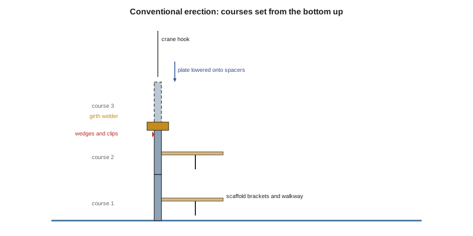
The conventional method suits large tanks, especially external floating roof tanks, because the floating roof can be built on legs on the bottom inside the shell while the courses rise around it. Its drawback is height: the crew works on scaffolds up to the top of the shell, with all the hazards of falls, dropped objects and wind that come with it. Imran's plan for Tank 15 sets up the scaffolds to a written design, requires fall protection everywhere outside the guarded walkways, controls the area under the work, and sets wind limits for lifting plates.
The jacking method
In the jacking method, the shell is built from the top down. The top course is erected first, on the bottom or on a temporary ring, and the roof framing and roof plates are built on it at ground level. Hydraulic jacks are then mounted on brackets around the inside of the shell, each jack climbing a column or a rod. The jacks lift the top course and roof together, a little more than one course height. The crew sets the next course of plates around the outside, below the lifted course, fits the horizontal seam, welds the vertical seams of the new course and then the horizontal seam above it. The jacks are moved down to grip the new course, and the cycle repeats until the last course, the bottom one, is set on the annular ring and welded to the bottom.
The great advantage is that almost all of the welding is done at ground level. There are no high scaffolds, the welders work in comfortable positions, and the roof, the most awkward part of a fixed-roof tank to build at height, is built at grade. The method needs a careful jacking plan: the jacks must share the load, the shell must stay level and round as it rises, and the lifted assembly must be stable against wind at every height. It is mostly used on fixed-roof tanks up to medium size, like T-31, and for raising existing tanks to replace their bottoms, as Kiera saw on Tank 14 in Rigging and Lifting for Boilermakers.
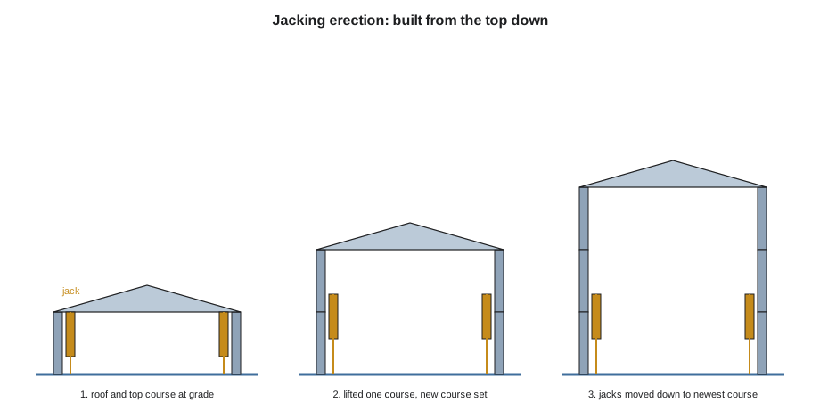
At Northgate, the jacking contractor's engineer, working with Rosa, plans T-31's lift. The tank is 80 ft in diameter, with five courses 8 ft high whose thicknesses run from 1/4 in at the top to 3/8 in at the bottom. The roof, rafters, top angle and platforms weigh about 84,000 lb. The jacks are rated at 10 tons each, the plan uses no more than 60 percent of each jack's rating, and the jacks may be no more than 8 ft apart on the shell, so that the thin shell is not overloaded between them. The output above shows the result: the weight rises from 52 tons on the first lift to 86 tons on the last, but 32 jacks are needed every time, because the spacing rule governs, not the capacity. With the jacks working well below their rating, a single jack that sticks or loses pressure does not overload its neighbors. Each lift of one course height takes 24 strokes.
During each lift, the jack operator watches every jack's stroke on the control console, and Hamid reads the level of the lifted course at eight points. If one side runs ahead of the other, the shell tilts and can twist, so the system stops after each stroke until the strokes are even. Between lifts, the shell is held on the jacks' mechanical locks, never on the hydraulic pressure alone.
Stability, wind and temporary support
An unfinished tank shell is weak. A course of thin plate standing on its own, without the stiffening of a roof or a wind girder, can be blown out of round or buckled by wind, and a partly erected shell is most vulnerable on its upper courses. Erection plans deal with this in three ways. Temporary wind girders or stiffening rings are fitted to the top of the shell as it rises. Guy cables or braces hold the shell where needed. And work stops when the wind exceeds the plan's limit: Bernie's plan for Tank 15 stops crane lifts of shell plates above 20 mph and requires the top of the shell to be braced every night.
The jacking method has its own stability question. A roof and top course lifted high on jacks are top-heavy, and a strong wind on the side of the shell pushes the whole assembly sideways on its jacks. The jacking plan includes lateral guides and a wind limit for each lift.
| Conventional method | Jacking method | |
|---|---|---|
| Order | Bottom course first, then upward | Top course and roof first, then downward |
| Where the welding is done | At every height, from scaffolds | Mostly at ground level |
| Roof | Built last, at the top; floating roofs built on the bottom | Built first, at grade |
| Best suited to | Large tanks, floating roof tanks | Fixed roof tanks of small to medium size; bottom replacements |
| Main hazards | Work at height, wind on plates, dropped objects | Jack failure, uneven lifting, wind on the lifted assembly |
Worked problem
Plates per course and seam stagger
A tank is 120 ft in diameter, and the longest shell plate available is 40 ft. How many plates are needed per course, how long is each, and what is a stagger of a third of a plate?
Show solution
- Circumference: π × 120 = 376.99 ft.
- Plates: 376.99 ÷ 40 = 9.4, so 10 plates.
- Plate length: 376.99 ÷ 10 = 37.70 ft.
- Stagger: 37.70 ÷ 3 = 12.57 ft.
Answer: 10 plates of 37.70 ft, staggered 12.57 ft.
Common mistakes
MistakeWelding the horizontal seam below a course before its vertical seams.
InsteadWeld each course's vertical seams first so that they can shrink freely, then the horizontal seam.
MistakeLetting the jacks run unevenly to save time.
InsteadStop after each stroke until all strokes are even; uneven lifting tilts and twists the shell.
MistakeLeaving the top of a partly erected shell unbraced overnight.
InsteadFit temporary stiffening or bracing; an unstiffened course can be blown out of round.
MistakeLining up vertical seams in adjacent courses.
InsteadStagger them by at least the standard's minimum, and usually by a third of a plate.
Summary and key terms
- Shell plates arrive rolled and marked; each course's vertical seams are staggered from the course below.
- The first course is set against guides on the annular ring and checked carefully, because every course follows it.
- In the conventional method, courses are set from the bottom up from scaffolds; girth and vertical welding machines are common on large tanks.
- In the jacking method, the roof and top course are built at grade and lifted on jacks while each new course is added below.
- Jack count is set by both capacity and spacing; the jacks must lift evenly.
- Partly erected shells are weak in wind and need temporary stiffening, bracing and wind limits.
- Conventional erection
- Building a tank shell from the bottom course upward.
- Jacking erection
- Building a tank shell from the top course downward by lifting it on jacks.
- Automatic girth welder
- A submerged arc machine that rides on the shell and welds horizontal seams.
- Electrogas welding
- An automatic process that welds a vertical seam full thickness in one upward pass.
- Seam stagger
- The offset between the vertical seams of adjacent shell courses.
- Temporary wind girder
- A stiffening ring fitted to a partly erected shell to keep it round in wind.
Practice problems
Work each problem on paper first, then reveal the answer to check.
Why are the vertical seams of a course welded before the horizontal seam below it?
Show answer
So that the vertical seams can shrink freely without being restrained by a finished horizontal seam.
Why did T-31 need the same number of jacks for every lift?
Show answer
Because the maximum jack spacing set the number, not the weight being lifted.
Name one advantage and one drawback of the jacking method.
Show answer
Advantage: most welding is done at ground level; drawback: the lifted assembly depends on the jacks lifting evenly and is exposed to wind.
A course is 8 ft high and the jacks travel 4 in per stroke. How many strokes lift it one course height?
Show answer
96 ÷ 4 = 24 strokes.
Lesson quiz · 5 questions
Score 60% or more to complete this lesson.
Create a free account to save your progress, take quizzes and earn a certificate.