
BLR-230 · Lesson 2 of 12 · 18 min
Tank types: fixed roof, floating roof and bolted tanks
On her first morning at Bayou Junction, Owen Kask walks Kiera along the tank farm road. There are twenty-two tanks in the terminal, built over fifty years, and almost every common type is here. "Every one of these was chosen for a reason," Owen says. "The product, the vapor pressure, the size, the climate, the money. If you know why a tank is the type it is, you know what matters when you build it or repair it." This lesson follows that walk and then looks at how the shell of a welded tank is designed, because the shell course thicknesses decide most of what the erection crew does.
Fixed roof tanks
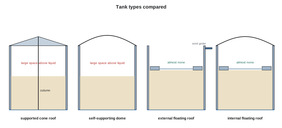
The simplest tank has a fixed roof. A cone roof is a shallow cone of thin plate, usually about 3/16 in thick, sloping up from the top of the shell to the center. Small cone roofs are self-supporting: the plate and a few rafters span from the shell to the center. Larger cone roofs rest on rafters that run from the shell to a ring of columns inside the tank, and the columns stand on the bottom. A dome roof is curved like a shallow sphere and supports itself from the shell, which keeps the inside of the tank free of columns. Aluminum geodesic domes, made of triangular panels bolted to a frame, are often fitted over old tanks to keep rain and snow off a floating roof.
A fixed roof tank has a vapor space between the liquid and the roof. When the tank is filled, the liquid pushes vapor out through the vents; when it is emptied or the sun heats the roof, air is drawn in. For products that give off little vapor, such as diesel, heavy fuel oil, asphalt or water, this does not matter much, and a fixed roof is the cheapest choice. For crude oil and gasoline, the vapor lost through the vents would be a large loss of product and a large source of air emissions, so those products go into floating roof tanks or into fixed roof tanks with a floating roof inside.
Fixed roof tanks also have a design feature that matters to the erection crew: the frangible roof joint. In many cone roof tanks, the weld between the roof plate and the top angle of the shell is made deliberately small, so that if an explosion inside the tank raises the pressure, the roof tears away from the shell before the shell tears from the bottom. That keeps the product inside the shell. The erector must make that weld exactly the size the drawing shows, no larger, and must not add strength around it, because a stronger roof joint can turn a roof failure into a bottom failure.
Floating roof tanks
A floating roof sits on the product and rises and falls with it, so there is almost no vapor space. An external floating roof tank has no fixed roof above the floating one; the floating roof is open to the sky. The roof is a steel deck stiffened by a ring of watertight compartments, the pontoons, around the outside, or by a double deck for very large tanks. Rainwater that falls on the roof drains through a hinged or flexible pipe inside the tank and out through a valve at the bottom of the shell. A gap of about 8 in between the roof rim and the shell is closed by a seal, usually a primary seal of steel shoes or foam with a secondary seal above it. Legs hold the roof up when the tank is emptied, so that the crew can work under it.
An internal floating roof tank is a fixed roof tank, often a dome or cone, with a light floating roof inside, usually aluminum pontoons with a thin deck. The fixed roof keeps rain and snow off the floating roof. Many older external floating roof tanks have been converted by adding a dome. Tank 15 will be an external floating roof tank with a pontoon roof, like Tank 14 beside it.
Bolted, shop-built and water tanks
Not every tank is welded in the field. In oil and gas production, small tanks that hold crude and produced water at well sites are often bolted tanks built to API 12B, made of curved steel panels bolted together with gaskets in the seams. They can be taken apart and moved when the wells are depleted. Small tanks up to about 12 ft in diameter are often welded in a shop and trucked to site, to API 12F, API 650 Annex J or a fabricator's listed standard. Water tanks for towns and fire protection are built to AWWA D100 if they are welded and AWWA D103 if they are bolted, with coating systems approved for drinking water.
Owen points out the terminal's two oldest tanks, which are riveted. Riveted tanks were common until the 1950s. A boilermaker today will not build one, but may well repair one, and the repair standards treat riveted seams with special care because the rivets cannot be welded.
| Type | Typical use | Key features for the erector |
|---|---|---|
| Supported cone roof | Diesel, fuel oil, water, slop oil | Rafters and columns; columns plumb; frangible roof joint |
| Self-supporting dome or cone | Small and medium product tanks | No columns; roof plate thickness and curvature set by design |
| External floating roof | Crude oil, gasoline, large tanks | Pontoon or double deck; seals; roof drain; wind girder; rolling ladder |
| Internal floating roof | Gasoline, light products, conversions | Fixed roof plus light floating deck; vents in the fixed roof |
| Bolted (API 12B) | Production sites | Gasketed seams; bolt torque; can be relocated |
| Welded water tank (AWWA D100) | Towns, fire protection | Drinking water coatings; disinfection after construction |
Choosing the type: vapor pressure and emissions
The product's vapor pressure decides most roof choices. Vapor pressure is the pressure at which a liquid boils at a given temperature; a liquid with a high vapor pressure gives off more vapor. In the United States, federal rules for volatile organic liquid storage vessels, such as the New Source Performance Standards in 40 CFR 60 Subpart Kb, require a floating roof or a closed vent system for tanks above set sizes that store liquids above set vapor pressures, and they set the seal gap limits that lesson 6 uses. Products with a very high vapor pressure, such as butane or propane, are stored in pressure vessels or spheres, not in atmospheric tanks.
Spill containment is the other rule every tank farm lives by. Tanks stand inside dikes or berms that hold the contents of the largest tank plus a margin, and many have leak detection under the bottom or a double bottom. In the United States, the EPA's Spill Prevention, Control, and Countermeasure rule in 40 CFR 112 requires plans, containment and regular tank inspection, and fire codes based on NFPA 30 set spacing and venting. The erector does not design the containment, but must not damage the dike, the liner or the leak detection, and must leave the tank ready for the inspection program that will follow it.
How the shell is designed: the one-foot method
Whatever the roof, the shell of a welded tank is designed for the hydrostatic pressure of its contents. The pressure at any depth is the product's density times gravity times the depth. A thin cylinder carries that pressure in hoop tension, and the required thickness is the hoop stress formula: pressure times radius divided by the allowable stress. API 650 sets the allowable stresses for each plate material and gives two methods for working out each course's thickness. The simpler one, the one-foot method, calculates the thickness at a point 1 ft above the bottom of each course, because the stiff course below helps hold the bottom of each course and the critical stress occurs a little above the seam. API 650 allows the one-foot method for tanks up to about 200 ft in diameter; larger tanks use the more exact variable design point method.
Here D is the diameter in feet, H is the design liquid level above the bottom of the course in feet, G is the design specific gravity of the product, Sd is the allowable design stress in pounds per square inch and CA is the corrosion allowance in inches; the answer is in inches. The standard also requires a hydrostatic test thickness, calculated the same way with water (G of 1), no corrosion allowance and the test stress St. The plate must be at least the larger of the two, and never less than a minimum thickness that depends on the diameter.
Owen hands Bernie the design for Tank 15, and Bernie asks Kiera to check the course thicknesses against it before the plate order is released. The design uses a plate grade with an allowable design stress of 28,000 psi and a test stress of 30,000 psi, values that are illustrative here, and the owner has asked for a corrosion allowance of 1/16 in and a design specific gravity of 0.9.
# One-foot method shell thicknesses for Tank 15 (US units, illustrative)
import math

d = 160.0              # diameter, ft
H = 48.0              # design liquid level, ft
course = 8.0        # course height, ft
G = 0.9              # design specific gravity of the crude
ca = 0.0625            # corrosion allowance, in
Sd, St = 28_000, 30_000  # allowable design and hydrotest stresses, psi
tmin = 0.3125        # minimum nominal thickness for this diameter, in

def plate(t):
    """Round up to the next available plate thickness."""
    return math.ceil(t / 0.0625 - 1e-9) * 0.0625

print("course  H at bottom   td      tt      plate")
for n in range(1, int(round(H / course)) + 1):
    hb = H - (n - 1) * course                 # liquid height above the bottom of this course
    td = 2.6 * d * (hb - 1) * G / Sd + ca
    tt = 2.6 * d * (hb - 1) / St
    t = max(plate(max(td, tt)), tmin)
print(f"{n:>4} {hb:8.0f} {td:6.3f} {tt:6.3f} {t:6.3f} in")course H at bottom td tt plate 1 48 0.691 0.652 0.750 in 2 40 0.584 0.541 0.625 in 3 32 0.477 0.430 0.500 in 4 24 0.370 0.319 0.375 in 5 16 0.263 0.208 0.312 in 6 8 0.156 0.097 0.312 in
The calculation gives a bottom course of 3/4 in, stepping down to 5/16 in for the top two courses, where the diameter's minimum thickness governs rather than the liquid. Owen's design matches. Kiera notices that for every course the design thickness, with its corrosion allowance and specific gravity, is greater than the hydrotest thickness, so the design condition governs. For a tank storing a light product with no corrosion allowance, the hydrotest thickness can govern instead.
The erection crew cares about these numbers for practical reasons. Each course is a different thickness, so each has its own welding procedure details, its own bevels and its own number of passes. The bottom course is the heaviest to handle and the thickest to weld. The thickness also decides how much radiography each course needs, as lesson 11 shows, and whether the vertical seams need preheat in cold weather.
Reading a tank data sheet
Every new tank starts from a data sheet, a standard form that the owner's engineer fills in and the tank designer and erector work from. API 650 includes a data sheet in its annexes, and most owners use it or their own version of it. For Tank 15, Owen's data sheet gives the diameter, height and capacity, the product and its design specific gravity, the design and test temperatures, the design wind speed and snow load, the corrosion allowances for the shell, bottom and roof, the plate materials, the roof type and seal types, and every appurtenance with its size, orientation and elevation. It also states the edition of API 650 and any annexes that apply, such as the annex for floating roofs. Kiera reads it before she reads anything else on the job, because every other drawing and calculation must agree with it, and when two documents disagree, it is usually the data sheet that settles the question or shows that someone has to ask.
Common mistakes
MistakeMaking the frangible roof weld bigger to be safe.
InsteadThe roof-to-shell weld is meant to fail first in an internal explosion; make it exactly the size shown.
MistakeAssuming a floating roof tank has no vapor space at all.
InsteadThere is a small space under the seal and at low levels when the roof lands on its legs; vents and procedures handle it.
MistakeUsing the same plate thickness for every course to keep things simple.
InsteadEach course is designed for its own liquid height; heavier plate is not always better, because it changes welding and NDE requirements.
MistakeIgnoring the diameter limit of the one-foot method.
InsteadLarger tanks are designed by the variable design point method, which gives different thicknesses.
Summary and key terms
- Fixed roof tanks suit low-vapor products; floating roofs suit crude oil and gasoline.
- External floating roofs are open to the sky; internal floating roofs sit under a fixed roof.
- Bolted tanks (API 12B), shop-built tanks and water tanks (AWWA D100, D103) each have their own standards.
- Vapor pressure and emission rules decide whether a floating roof or vapor control is needed; containment rules apply to every tank farm.
- The one-foot method sizes each course for the liquid height above a point 1 ft above its bottom.
- The plate must meet the larger of the design and hydrotest thicknesses and the minimum for the diameter.
- Cone roof
- A shallow conical fixed roof, self-supporting or carried on rafters and columns.
- External floating roof
- A roof that floats on the product with no fixed roof above it.
- Pontoon
- A watertight compartment that gives a floating roof its buoyancy.
- Frangible roof joint
- A deliberately weak roof-to-shell joint that fails before the shell-to-bottom joint.
- One-foot method
- The API 650 method that sizes each course at a point 1 ft above its bottom.
- Corrosion allowance
- Extra thickness added to allow for metal lost to corrosion in service.
Practice problems
Work each problem on paper first, then reveal the answer to check.
Why does crude oil usually go into floating roof tanks?
Show answer
Because its vapor pressure is high enough that a fixed roof tank would lose a lot of vapor through its vents.
What is the purpose of the frangible roof joint?
Show answer
It lets the roof tear from the shell in an internal explosion before the shell tears from the bottom, so the product stays in the shell.
Using the one-foot method, what is the design thickness of a course with 33 ft of liquid above its bottom, in a 130 ft tank with G = 0.9, Sd = 28,000 psi and no corrosion allowance?
Show answer
2.6 × 130 × 32 × 0.9 ÷ 28,000 = 0.348 in.
Name two standards for water storage tanks.
Show answer
AWWA D100 for welded tanks and AWWA D103 for bolted tanks.
Lesson quiz · 5 questions
Score 60% or more to complete this lesson.
Create a free account to save your progress, take quizzes and earn a certificate.