
BLR-220 · Lesson 9 of 12 · 19 min
Shell-and-tube heat exchangers
Northgate's fall turnaround begins in October, and more than two hundred heat exchangers are on its list. Most will be opened, cleaned, inspected and closed. Some will have tubes plugged. A few will be retubed or replaced. E-1105, which heats crude oil with hot diesel product before the crude goes to the furnace, is one of the few. Ruth Ambrose, Northgate's fixed equipment engineer, shows Rosa Delgado and Kiera its history: the bundle is nineteen years old, its tubes were inspected by eddy current at the last turnaround, and the readings showed wall loss on the outside of many tubes near the baffles. Since then, enough tubes have been plugged to pass the plant's limit. The bundle will be pulled at site, trucked to Ironbridge's exchanger shop and retubed.
Shell-and-tube exchangers are the most common heat exchangers in refineries, chemical plants, power plants and pulp mills, and boilermakers do most of the mechanical work on them. This lesson explains how they are built, how they are named, how their heat duty is worked out, and how they are opened and inspected.
How a shell-and-tube exchanger works
One fluid flows through the tubes, the tube side, and the other flows around them inside the shell, the shell side. Heat passes through the tube walls from the hotter fluid to the colder one. The tube side fluid enters a channel at the front end, flows through the tubes and returns through another set of tubes if the channel is divided by pass partition plates into two or more passes. The shell side fluid enters through a nozzle on the shell and is forced back and forth across the tubes by baffles, plates with part of their circle cut away, so it flows across the tubes rather than straight along them. The baffles also support the tubes and stop them vibrating.
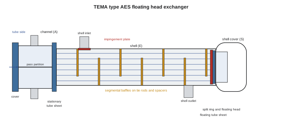
The fluid that is more corrosive, at higher pressure, dirtier or more likely to foul usually goes in the tubes, because tubes are easier to clean and cheaper to make of expensive alloys than a shell. In E-1105, the crude, which fouls, goes in the tubes, and the cleaner diesel goes in the shell.
TEMA types and classes
The Tubular Exchanger Manufacturers Association, TEMA, publishes the standards most shell-and-tube exchangers are built to. The current edition is the tenth, published in 2019. TEMA names every exchanger with three letters: the front head type, the shell type and the rear head type. E-1105 is an AES: an A front head, a channel with a removable cover; an E shell, a one-pass shell with the nozzles at opposite ends; and an S rear head, a floating head with a backing device.
| Letter position | Common types | What they mean |
|---|---|---|
| Front head | A, B, C, N | A: channel with removable cover. B: bonnet. C and N: channel integral with the tube sheet. |
| Shell | E, F, G, H, J, K, X | E: one-pass shell. F: two-pass shell with a long baffle. K: kettle reboiler. J and X: divided and cross flow. |
| Rear head | L, M, N, P, S, T, U, W | L, M, N: fixed tube sheet. S: floating head with backing device. T: pull-through floating head. U: U-tube bundle. |
TEMA also sets three classes of mechanical standard: class R, for the generally severe requirements of petroleum and related processing; class C, for the generally moderate requirements of commercial and general process service; and class B, for chemical process service. Refineries usually buy class R exchangers, often with the additional requirements of API Standard 660, the American Petroleum Institute's standard for shell-and-tube exchangers in petroleum and natural gas service, whose current edition dates from 2015 with an addendum in 2020.
Fixed, U-tube and floating head designs
The tubes and the shell run at different temperatures, so they grow by different amounts. How an exchanger copes with that is its most important design choice.
- Fixed tube sheet (L, M or N rear head). Both tube sheets are welded to the shell. It is the cheapest design, but the tube bundle cannot be removed, the shell side can be cleaned only chemically, and differential growth must be small or taken by an expansion joint in the shell.
- U-tube (U rear head). One tube sheet; the tubes are bent into U shapes and grow freely. The bundle can be pulled, but the inside of the bends cannot be cleaned mechanically and individual inner tubes are hard to replace.
- Floating head (S or T rear head). The rear tube sheet is not attached to the shell; it floats inside the shell cover with its own floating head cover, so the bundle can grow freely and can be pulled for cleaning. In an S type, the floating head cover is clamped to the floating tube sheet by a split backing ring, so the shell cover must be removed first. In a T type, the floating head is bolted directly to the tube sheet and the whole bundle pulls through the shell.
Floating head exchangers are the workhorses of refineries because both sides can be cleaned mechanically. They are also the most work to open: the channel cover, the channel, the shell cover, the split ring and the floating head cover all come off before the bundle can be pulled.
Working out the duty
The heat duty is the heat transferred per hour, and it can be worked out from either fluid: flow times specific heat times temperature change. The heat passing through the tubes is the overall coefficient times the area times a temperature difference. Because the temperature difference between the fluids changes along the exchanger, the right average is the log mean temperature difference, LMTD:
Here the two terms are the temperature differences at each end of the exchanger. For an exchanger with two tube passes, the flow is not pure counterflow, so the LMTD is multiplied by a correction factor F read from a chart, usually between about 0.8 and 1.0. Ruth gives Kiera E-1105's design data so she can see how many tubes the duty needs.
# E-1105 diesel / crude exchanger: duty, LMTD and the tubes the area needs (US units)
import math

m_hot, cp_hot = 209_000, 0.62        # diesel, shell side: lb/h and Btu/lb F
t_hot_in, t_hot_out = 554, 356
m_cold, cp_cold = 330_000, 0.55      # crude, tube side
t_cold_in = 248

q = m_hot * cp_hot * (t_hot_in - t_hot_out)          # heat given up by the diesel
t_cold_out = t_cold_in + q / (m_cold * cp_cold)
print(f"Duty: {q / 1e6:,.2f} MMBtu/h")
print(f"Crude leaves at {t_cold_out:.0f} °F")

dt1 = t_hot_in - t_cold_out      # hot end
dt2 = t_hot_out - t_cold_in      # cold end
lmtd = (dt1 - dt2) / math.log(dt1 / dt2)
print(f"Terminal differences {dt1:.0f} and {dt2:.0f} °F; counterflow LMTD {lmtd:.1f} °F")

F = 0.90                          # correction for one shell pass, two tube passes (from the chart)
U = 70.4                           # overall coefficient with fouling, Btu/h ft2 F
area = q  / (U * F * lmtd)
per_tube = math.pi * 0.75 / 12 * 19.65
print(f"Area needed: {area:,.0f} ft2; one tube gives {per_tube:.3f} ft2")
print(f"Tubes needed: {area / per_tube:.0f} (the bundle has 793)")Duty: 25.66 MMBtu/h Crude leaves at 389 °F Terminal differences 165 and 108 °F; counterflow LMTD 134.3 °F Area needed: 3,014 ft2; one tube gives 3.858 ft2 Tubes needed: 781 (the bundle has 793)
The duty needs about 785 tubes' worth of area and the bundle has 793, which tells Kiera why the plant cannot simply keep plugging tubes: every plugged tube takes area away, and with more than one in ten plugged, E-1105 could no longer heat the crude enough, so the furnace downstream had to burn more fuel. The overall coefficient used here includes an allowance for fouling. A fouled exchanger has a lower coefficient, and its performance falls even with every tube in service, which is why exchangers are cleaned at every turnaround.
Opening, cleaning and inspecting
At a turnaround, an exchanger is isolated, drained, purged and blinded, then opened. Boilermakers remove the covers and heads and pull the bundle with a bundle extractor, a hydraulic machine that sits on the shell flange or hangs from a crane and pulls the bundle out onto a cradle. The bundle goes to the wash pad, where the tube side and the outside of the tubes are cleaned with high-pressure water. Then the inspectors go to work.
| Inspection | What it finds |
|---|---|
| Visual inspection of tube sheets, baffles and shell | Corrosion, erosion, baffle wear, cracking |
| Eddy current testing (ECT) of non-magnetic tubes | Wall loss, pitting and cracks along each tube |
| Remote field testing or IRIS ultrasonic rotary inspection of steel tubes | Wall loss in carbon steel tubes; IRIS measures thickness directly |
| Hydrostatic test of the shell side with the channel off | Leaking tubes and tube-to-tube sheet joints |
| Thickness readings on the shell, channel and nozzles | General corrosion |
Leaking tubes are found by testing the shell side with the tube ends exposed and watching for water coming out of a tube end or a joint. Each leaking tube is plugged at both ends, recorded on a tube sheet map, and counted against the plant's plugging limit. E-1105's map shows the plugged tubes clustered near the shell side inlet nozzle, under the impingement plate, and in rows next to the baffle cuts, where the diesel flows fastest. Ruth's conclusion is that the tube wall loss is erosion-corrosion on the outside of the tubes, and she has specified a larger impingement plate for the new bundle while keeping the same tube size, so its thermal performance is unchanged.
When the exchanger is put back together, its bolted joints are assembled to a procedure: new gaskets of the type specified, bolts lubricated, and tightening in a pattern in several rounds to a target load, following the practices in ASME PCC-1 for bolted flange joint assembly. Lesson 11 covers the tests that prove it tight.
Worked problem
Log mean temperature difference
Hot oil enters an exchanger at 390 °F and leaves at 250 °F. Cooling water enters at 85 °F and leaves at 140 °F in counterflow. What is the LMTD?
Show solution
- Hot end difference: 390 − 140 = 250 °F.
- Cold end difference: 250 − 85 = 165 °F.
- LMTD: (250 − 165) ÷ ln(250 ÷ 165) = 85 ÷ 0.416 = 204 °F.
Answer: About 204 °F.
Pulling a bundle safely
Pulling a bundle is one of the heaviest and most dangerous jobs in a turnaround. E-1105's bundle weighs about 10 tons and is 20 ft long, and it is pulled from a shell on a structure 16 ft above grade. The extractor is a hydraulic frame that is hung from a crane and bolted to the shell flange; its pulling bars are attached to the stationary tube sheet through the bundle's pulling eyes or bolted pulling plates, never by threading slings through the tubes. As the bundle slides out, the extractor carries its weight on its own rails, and when it is clear of the shell, the crane lowers the whole extractor and bundle to a cradle or truck. The lift is planned like any critical lift, with the bundle weight from the data sheet plus an allowance for deposits, which can add a lot of weight to a fouled bundle.
Bundles can stick in their shells when the baffles or the floating head have corroded or fouled against the shell. The extractor's pressure gauge shows the pulling force, and the lift plan sets a limit. If a bundle sticks, the crew stops, investigates and frees it by cleaning or by working it gently, rather than pulling harder and damaging the tube sheet or the shell. At Northgate, E-1105 comes out at a moderate force, and the bundle's outer tubes show the erosion pattern Ruth expected near the inlet nozzle.
Common mistakes
MistakePulling a bundle by hooking slings around the tubes.
InsteadPull by the tube sheet with the extractor or the bundle's pulling eyes; slings on tubes crush them.
MistakeRemoving an S type floating head without first removing the shell cover.
InsteadThe shell cover comes off first to reach the split ring and floating head.
MistakeReassembling with old gaskets or random bolt tightening.
InsteadUse new gaskets of the specified type and tighten to the joint assembly procedure.
MistakePlugging tubes without recording them on the tube sheet map.
InsteadEvery plug is mapped and counted against the plugging limit.
Summary and key terms
- One fluid flows through the tubes and the other through the shell; baffles force the shell fluid across the tubes and support them.
- TEMA names exchangers by front head, shell and rear head letters, and sets classes R, C and B.
- Fixed tube sheet, U-tube and floating head designs deal with differential growth in different ways.
- Duty is flow times specific heat times temperature change, and equals U times area times the corrected LMTD.
- Bundles are pulled with extractors, cleaned and inspected by ECT, IRIS or remote field testing and a shell side test.
- Plugged tubes reduce area; past the plant's limit, the bundle is retubed.
- Tube side
- The fluid path through the tubes, channels and heads.
- Shell side
- The fluid path around the tubes inside the shell.
- Baffle
- A plate that directs the shell side flow across the tubes and supports them.
- Floating head
- A rear tube sheet and cover free to move inside the shell as the bundle grows.
- LMTD
- Log mean temperature difference: the effective average temperature difference across an exchanger.
- Eddy current testing
- An electromagnetic method of finding wall loss and cracks in non-magnetic tubes.
Practice problems
Work each problem on paper first, then reveal the answer to check.
What does the designation AES tell you?
Show answer
A channel with a removable cover, a one-pass shell and a floating head with a backing device.
Why does the fouling fluid usually go in the tubes?
Show answer
Tubes are easier to clean than the shell side.
An exchanger needs 3,200 ft2 of area and each tube gives 3.86 ft2. How many tubes are needed?
Show answer
About 829.
Where did E-1105's tube failures cluster, and why?
Show answer
Near the shell inlet nozzle and next to the baffle cuts, where the diesel flows fastest and erodes the tubes.
Lesson quiz · 5 questions
Score 60% or more to complete this lesson.
Create a free account to save your progress, take quizzes and earn a certificate.