
BLR-220 · Lesson 12 of 12 · 20 min
Capstone: retubing a heat exchanger bundle
On the fourth day of Northgate's turnaround, a flatbed backs into Ironbridge's exchanger shop at Port Allen with E-1105's bundle strapped to a cradle. It is 20 ft of tubes between two tube sheets, with its baffles, tie rods and the remains of a nineteen-year-old impingement plate, and it weighs about 10 tons. Northgate wants it back in eight days, retubed, tested and ready to go back into its shell. Desmond Pryce leads the job. Kiera is on his crew for all of it, and Rosa Delgado has told her that at the end she is to write the job summary that goes to Ruth Ambrose with the records. This capstone follows the retube from the specification to the bundle going back into service, and brings together the tube sheets and layout of lesson 8, the exchanger of lesson 9 and the testing of lesson 11.
The retube specification
Ruth's specification sets out what Ironbridge must do and what must come back. The tube sheets, baffles and tie rods will be reused if they pass inspection; the tubes and the impingement plate are new. The tubes are seamless cold-drawn carbon steel to SA-179, 3/4 in outside diameter, 0.083 in minimum wall, 14 BWG, with material test reports. They are expanded into both tube sheets, without welding, to a wall reduction of 5 to 8 percent, with the inside diameters of at least one tube in ten measured and recorded and every tube in the first rows measured until the tool settings are proven. The rolled length stops 1/8 in from the shell side face of each tube sheet. The bundle is tested on the shell side with a test ring, and the tube side is tested after the bundle is back in its shell. Every step is recorded on Ironbridge's traveler, and Ruth or her inspector witnesses the tests.
Desmond starts with the numbers. The code below works out the material order from the tube count and cut length, then checks the roll-in records the crew will produce, using a sample from the first day, and gives the two test pressures from the exchanger's nameplate.
# E-1105 retube: material list, roll-in records and the test pressures (US units)
import math
tubes = 793
od, wall = 0.750, 0.083              # in
length = 20.02                        # cut length, ft
spare = math.ceil(tubes * 1.03)
mass = math.pi * (od - wall) * wall * 0.2836 * 12     # mass per unit length, lb/ft
print(f"Order {spare} tubes ({spare - tubes} spares), {tubes * length:,.0f} ft in the bundle, about {tubes * length * mass:,.0f} lb")

# Roll-in records: tube, hole diameter, inside diameter before and after rolling (in)
recs = [
    ("F-001", 0.7600, 0.5840, 0.6050),
    ("F-002", 0.7605, 0.5845, 0.6062),
    ("F-057", 0.7590, 0.5826, 0.5990),
    ("F-058", 0.7602, 0.5842, 0.6054),
    ("F-214", 0.7600, 0.5836, 0.6083),
    ("F-215", 0.7596, 0.5838, 0.6046),
]
lo, hi = 0.05, 0.08
for tube, hole, id0, idf in recs:
    wr = ((idf - id0) - (hole - od)) / (2 * wall)
    if wr < lo:
        verdict = "under-rolled: re-roll and re-measure"
    elif wr > hi:
        verdict = "over-rolled: hold for the owner's engineer"
    else:
        verdict = "accept"
    print(f"{tube:>6}  wall reduction {wr:5.1%}  {verdict}")

shell_mawp, tube_mawp = 300, 500   # psi
print(f"Shell side test (tube joints visible): {1.3 * shell_mawp:,.0f} psi")
print(f"Tube side test with the bundle in the shell: {1.3 * tube_mawp:,.0f} psi")Order 817 tubes (24 spares), 15,876 ft in the bundle, about 9,397 lb F-001 wall reduction 6.6% accept F-002 wall reduction 6.7% accept F-057 wall reduction 4.5% under-rolled: re-roll and re-measure F-058 wall reduction 6.6% accept F-214 wall reduction 8.9% over-rolled: hold for the owner's engineer F-215 wall reduction 6.7% accept Shell side test (tube joints visible): 390 psi Tube side test with the bundle in the shell: 650 psi
The order is 817 tubes, a 3 percent margin for tubes damaged during installation. The cut length of 20.02 ft gives each tube a projection of 1/8 in beyond each tube sheet face. The roll records and the test pressures are discussed below, where the crew meets them.
Taking the old tubes out
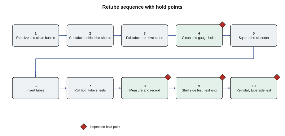
The bundle is steam cleaned on the wash pad and set level on the cradle. The crew cuts the tubes just behind each tube sheet, on the shell side, with an internal cutter run in from the tube side, then pulls the long middle sections out with the tube puller, a hydraulic jaw that grips the tube end and draws it out through the baffles. The tube stubs left in the tube sheets are collapsed inward with a stub-collapsing tool, a narrow chisel driven along the inside of the stub to fold it away from the hole wall, and knocked or pulled out. Desmond allows no torches anywhere near the tube sheets: a single gouge in a hole wall leaves a leak path the new tube cannot close.
The old tubes go into a scrap bin, except for six that Ruth wants cut into sections and sent to Northgate's lab so its metallurgist can confirm the cause of the wall loss on the outside of the tubes near the inlet.
Inspecting the tube sheets and skeleton
With the tubes out, every hole is cleaned to bright metal with a hole brush and inspected. Kiera gauges the holes with a dial bore gauge, recording the diameter of every hole in the first rows and a sample of the rest on a tube sheet map. Most holes measure 0.759 to 0.761 in, within the standard tolerance for a 0.760 in hole. Nine holes near the inlet side of the floating tube sheet are slightly oversized and have shallow grooves left by the old joints. Ruth reviews the map and accepts them, on condition that their roll records are kept separately. The tube sheets are checked for flatness, the ligaments are examined by liquid penetrant for cracks, and the gasket faces and pass partition grooves are inspected; one gasket face needs a light skim cut in the machine shop.
The baffles show wear at the holes nearest the inlet, where the old tubes vibrated against them, but the holes are within the specification's limit for reuse. The tie rods and spacers are sound. A new, larger impingement plate is fitted to Ruth's drawing. The skeleton, the tube sheets, baffles, tie rods and spacers, is squared up on the cradle and the baffle holes are lined up with the tube sheet holes by pushing guide rods through each row.
Installing and rolling the new tubes
The new tubes arrive with capped ends and their material test reports, which Harjit Gill checks against the specification before any tube goes in. Each tube's ends are cleaned and lightly polished on the outside where they will sit in the holes. The tubes are pushed through by hand from the stationary end, guided through the baffles with a bullet-nosed tip, and set with the projection checked by a gauge at both ends.
Rolling starts at the stationary tube sheet. Desmond sets the expander's torque control on a test block to give about 7 percent wall reduction, then rolls the first row and measures every tube. He rolls in a pattern that spreads the work across the tube sheet, a few tubes in one area and then a few in the opposite area, rather than marching row by row from one side, so the tube sheet is not pushed out of flat by the joints all being made on one side first. When the stationary sheet is done, the crew moves to the floating sheet, where each tube is again checked for projection before rolling.
The day's roll records produce the results the code above checked. Most tubes fall between about 5.5 and 7 percent. Tube F-057, in one of the oversized holes Ruth accepted, is under-rolled at about 4.5 percent; the crew re-rolls it and it measures 6.1 percent. Tube F-214 is over-rolled at about 9 percent: its rolled inside diameter is larger than the specification allows, probably because the operator held the expander a few seconds too long. Ruth is called. She does not accept an over-rolled joint in a bundle that will run for twenty years, so F-214 is cut out, its hole is gauged and found still within tolerance, and a new tube is installed and rolled to 6.8 percent. The two neighboring joints are checked for loosening by measurement and pass.
| Record | What it shows |
|---|---|
| Tube sheet hole map | Every measured hole diameter, oversized holes marked and accepted |
| Material test reports | The tubes meet SA-179 and the size ordered |
| Roll records | Inside diameter before and after, hole diameter and wall reduction for each measured tube |
| Non-conformance report | F-214 over-rolled, replaced; F-057 re-rolled; disposition signed by Ruth |
| Test records | Shell side and tube side test pressures, hold times, results, witnesses |
| Traveler | Every step and hold point signed off |
Testing
When rolling is finished, the bundle is put into Ironbridge's test shell, a spare shell of the same size kept for testing bundles, and the test ring is bolted to the floating tube sheet so that both tube sheets' faces, with every tube end, are visible. The shell side is filled with water, vented, and brought up in steps to the shell side test pressure of 390 psi, 1.3 times the shell's MAWP, as the code calculated, because the shell's steel has the same allowable stress at its design temperature as at room temperature. Ruth's inspector watches the tube sheets with the crew from outside the barricade during the hold, then closely at the inspection pressure.
Two joints weep at the floating tube sheet: small beads of water at the tube end, which grow slowly. The pressure is released, the bundle is drained to below the joints, and the two tubes are re-rolled lightly, by about half a percent more wall reduction, which keeps them within the limit. The test is repeated, and this time every joint is dry through the hold. The test record is signed.
Back at Northgate, the bundle goes into its own shell with new gaskets. The floating head, the shell cover, the channel and the channel cover are assembled and the bolting is tightened to Northgate's joint assembly procedure. The tube side is then filled and tested at 650 psi, 1.3 times the tube side MAWP, which proves the floating head joint and the tube side gaskets. With that test passed, E-1105 is turned over to operations, which heat it up slowly and check its flanges for leaks as it comes up to temperature.
Writing the job summary
Kiera's summary for Ruth fits on one page with the records attached. It states the scope, what was found when the bundle was opened, the decisions made on the oversized holes and the two problem tubes, the test results and the final count: 793 tubes installed, none plugged, wall reductions within 5 to 8 percent on every measured tube. It lists one recommendation for the next turnaround, from the lab report on the old tubes, which confirms erosion-corrosion at the shell inlet: inspect the tubes under the new impingement plate first. Ruth adds the summary to E-1105's file, where the next crew to open the exchanger will find it.
The job also closes the course's loop. The fire-tube boiler at Larkspur, the drum internals and headers at Riverbend, the HRSG at Northgate, V-412's nozzles and test, and E-1105's bundle are all the same kind of work: understand what the equipment does, take it apart without damaging it, measure and record what matters, put it back to the drawing and the procedure, and prove it with a test. Next, BLR-230 takes Kiera out of the shop and into the field to erect storage tanks, stacks and large structures.
Worked problem
Checking a roll record
A tube sits in a 0.7605 in hole. Its inside diameter is 0.5845 in before rolling and 0.6062 in after. The tube is 0.750 in by 0.083 in. Is the joint within 5 to 8 percent?
Show solution
- Growth of the inside diameter: 0.6062 − 0.5845 = 0.0217 in.
- Clearance: 0.7605 − 0.750 = 0.0105 in.
- Wall reduction: (0.0217 − 0.0105) ÷ 0.166 = 6.7 percent.
Answer: Yes, about 6.7 percent. This is tube F-002 in the code's records.
Common mistakes
MistakeUsing a torch to free tube stubs from a tube sheet.
InsteadCollapse and pull stubs mechanically so the holes are not gouged.
MistakeRolling a tube sheet row by row from one edge.
InsteadRoll in a pattern across the sheet so it stays flat.
MistakeAccepting an over-rolled joint because it does not leak today.
InsteadReport it; over-rolled joints are dispositioned by the owner's engineer.
MistakeRe-rolling a weeping joint while the shell side is under pressure.
InsteadRelease the pressure and drain below the joint before re-rolling, then retest.
MistakeSending the bundle back without its records.
InsteadThe hole map, roll records, material reports, test records and traveler go with the bundle.
Summary and key terms
- A retube follows a written specification for tubes, wall reduction, measurement, testing and records.
- Old tubes are cut, pulled and their stubs collapsed without damaging the holes.
- Holes are cleaned, gauged, mapped and inspected, and the skeleton is checked and squared before new tubes go in.
- Tubes are rolled in a pattern to a proven tool setting, measured and recorded; out-of-range joints are dispositioned by the owner.
- A shell side test with a test ring shows every tube end; a tube side test after reassembly proves the heads and gaskets.
- The job summary and records return to the owner and become part of the equipment's history.
- Retube
- Replacing all the tubes in a boiler or exchanger bundle.
- Skeleton
- The tube sheets, baffles, tie rods and spacers of a bundle without its tubes.
- Stub-collapsing tool
- A narrow chisel used to fold a tube stub away from its hole so it can be removed.
- Test shell
- A spare shell used to pressure test bundles in the shop.
- Non-conformance report
- A record of work that does not meet the specification and how it was dispositioned.
- Traveler
- The record sheet that follows a job through each step and hold point.
Practice problems
Work each problem on paper first, then reveal the answer to check.
Why does Desmond allow no torches near the tube sheets?
Show answer
A torch can gouge or burn a hole wall, leaving a leak path that the new tube cannot seal.
Why are the inside diameters of the first rows all measured?
Show answer
To prove that the expander setting gives the required wall reduction before sampling the rest.
What is the shell side test pressure of an exchanger with a shell MAWP of 300 psi and a stress ratio of 1.0?
Show answer
390 psi.
Name three records that go back to the owner with a retubed bundle.
Show answer
The hole map, the roll records, the material test reports, the test records, the non-conformance reports and the traveler.
Lesson quiz · 5 questions
Score 60% or more to complete this lesson.
Create a free account to save your progress, take quizzes and earn a certificate.