
MEC-280 · Lesson 7 of 12 · 21 min
Grinding, finishing and surface integrity
The bearing journals of the KG-40 output shaft must be round within a few micrometres, sized to a tolerance of 16 µm and smooth enough, about Ra 0.4 µm, for the bearing inner rings and the lip seal to run on them. Turning cannot reliably reach that combination after the shaft is induction hardened to 55 HRC. Grinding can. This lesson covers abrasive processes, how surface roughness is described and predicted, the finishing processes that follow grinding, and surface integrity: the hidden condition of the layer just below the surface, which decided the fate of the PTO shaft in MEC-250.
Describing surface texture
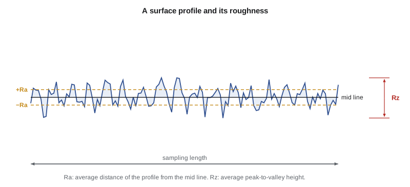
No machined surface is perfectly smooth. Under magnification, it shows roughness, the fine closely spaced marks left by the tool or abrasive grains; waviness, longer undulations from vibration, deflection or spindle error; and lay, the dominant direction of the marks. A stylus profilometer drags a fine diamond tip across the surface and records its height. From the profile, after filtering out waviness with a cutoff length, typically 0.8 mm, the instrument computes roughness parameters.
The arithmetic average roughness \(R_a\) is the mean absolute deviation of the profile from its centre line. It is the parameter most drawings specify, in micrometres in metric practice or microinches in US practice (1 µm = 39.4 µin). \(R_z\), the average peak-to-valley height, is larger, typically four to seven times \(R_a\), and is more sensitive to isolated scratches. Neither parameter tells the whole story: two surfaces with the same \(R_a\) can have sharp peaks or rounded plateaus that behave very differently in sealing or wear, which is why bearing and seal surfaces sometimes carry additional parameters.
| Process | Typical Ra (µm) | Typical Ra (µin) |
|---|---|---|
| Sand casting | 6.3 to 25 | 250 to 1000 |
| Rough turning, milling | 3.2 to 12.5 | 125 to 500 |
| Finish turning, milling | 0.8 to 3.2 | 32 to 125 |
| Reaming, boring | 0.8 to 3.2 | 32 to 125 |
| Cylindrical grinding | 0.2 to 1.6 | 8 to 63 |
| Honing | 0.05 to 0.4 | 2 to 16 |
| Lapping, superfinishing | 0.025 to 0.2 | 1 to 8 |
| Polishing | 0.025 to 0.4 | 1 to 16 |
Predicting the finish from a turning tool
In turning, the tool's nose radius \(r_\varepsilon\) leaves a series of arcs, one for each revolution, spaced by the feed \(f\). Simple geometry gives the height of the cusps and an ideal roughness.
Halving the feed cuts the ideal roughness by a factor of four; doubling the nose radius halves it. Real surfaces are rougher than the ideal because of tool wear, built-up edge, vibration and material side flow, often by 50 percent or more for steels at moderate speeds, but the formula is a good guide for choosing finishing feeds. For the shaft's seal surface, which is turned to Ra 1.6 µm before grinding, a 0.8 mm nose radius and a feed of 0.18 mm/rev give an ideal Ra of 1.27 µm, leaving margin for real-world effects.
Grinding
A grinding wheel is a bonded mass of hard abrasive grains with pores between them. Each grain that touches the work acts as a tiny cutting tool with a large negative rake angle, taking a minute chip. Thousands of grains cut per second at wheel surface speeds of 25 to 45 m/s for conventional wheels and up to 120 m/s or more for special high-speed wheels. Because the chips are tiny, grinding can achieve fine finishes and tight tolerances, and because the grains are extremely hard, it cuts hardened steels, ceramics and carbides that defeat ordinary tools.
Grinding wheels are specified by abrasive, grain size, grade, structure and bond. Aluminum oxide is the common abrasive for steels; silicon carbide suits cast iron, nonferrous metals and nonmetals; cubic boron nitride and diamond, the superabrasives, grind hardened steels and carbides respectively with very long wheel life. Grain size runs from coarse (around 24 mesh) for fast stock removal to fine (180 and finer) for finishing. Grade describes how strongly the bond holds the grains: a hard wheel holds them long, a soft wheel releases them sooner. The rule of thumb is a soft wheel for hard materials, so that dull grains break out and expose sharp new ones, and a hard wheel for soft materials. Vitrified (glassy) bonds are rigid and porous; resin bonds are tougher and used for cut-off wheels; metal bonds hold superabrasive grains.
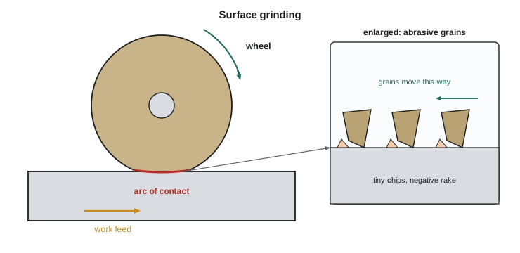
The common grinding operations mirror machining. Surface grinding produces flat faces, with the work reciprocating under the wheel. Cylindrical grinding produces outside diameters between centres; plunge grinding feeds a wide wheel straight in, while traverse grinding moves the work past the wheel. Internal grinding finishes bores with a small wheel on a fast spindle. Centreless grinding supports the work on a rest blade between the grinding wheel and a regulating wheel that controls its rotation, allowing very high rates for pins, rollers and small shafts without centre holes. Creep-feed grinding takes a full-depth cut in one slow pass and can replace milling for profiles in hard materials.
Grinding energy and burn
Grinding uses far more energy per unit volume than turning, often 20 to 60 J/mm³ for hardened steel compared with 2 to 4 J/mm³ for turning. The grains' negative rake, rubbing and ploughing waste most of it, and nearly all of it becomes heat in a very thin surface layer. Because the chips are tiny, less heat leaves with them than in turning. If the surface gets too hot, grinding burn results: temper colours, softening of the hardened layer, rehardening into brittle untempered martensite in severe cases, and tensile residual stresses that can start fatigue cracks. Burn can be invisible, so critical parts are checked by nital etching or Barkhausen noise inspection.
Engineers control burn with sharp, free-cutting wheels, ample coolant directed into the contact zone, moderate infeed rates and spark-out passes with zero infeed at the end of the cycle to remove the last thin layer gently. Wheels must be dressed periodically with a diamond tool to restore sharp grains and true their shape.
Worked problem
Grinding power and burn risk on the journal
The 40 mm journal is plunge ground with a 30 mm wide wheel. The radial stock is 0.15 mm, removed at an infeed rate of 0.6 mm/min on radius, with the shaft turning at 120 rpm. The specific energy for this hardened 4140 and wheel is 35 J/mm³. Find the material removal rate, the grinding power and the power per millimetre of wheel width.
Show solution
- Removal rate: circumference × width × radial infeed rate \(= \pi(40)(30)(0.6) = 2262\ \text{mm}^3/\text{min} = 37.7\ \text{mm}^3/\text{s}\).
- Power: \(P = u \cdot \text{MRR} = 35(37.7) = 1319\ \text{W}\).
- Per millimetre of width: \(1319/30 = 44\ \text{W/mm}\).
- Plunge time for the stock: \(0.15/0.6 = 0.25\ \text{min}\), plus about 5 s of spark-out.
Answer: About 1.3 kW, or 44 W per millimetre of width. The wheel supplier's guidance for this wheel and coolant is to stay below about 60 W/mm to avoid burn, so the infeed is acceptable; doubling it would approach the limit.
# Surface finish and grinding power for the KG-40 output shaft
import math

# Ideal turned roughness, Ra = f^2 / (32 r)
print("Ideal Ra (um) for feed (mm/rev) and nose radius (mm)")
radii = (0.4, 0.8, 1.2)
print(" feed  " + "".join(f"  r={r:<4}" for r in radii))
for f in (0.08, 0.12, 0.18, 0.25, 0.35):
    print(f"{f:5.2f}  " + "".join(f"{f**2 / (32 * r) * 1000:8.2f}" for r in radii))

# Plunge grinding the 40 mm journal
D, b = 40.0, 30.0            # journal diameter, wheel width (mm)
u = 35.0                     # specific grinding energy, J/mm^3
stock = 0.15                 # radial stock, mm
limit = 60.0                 # W per mm of wheel width, burn guideline for this wheel and coolant

def grind(infeed):           # infeed in mm/min on radius
    mrr = math.pi * D * b * infeed / 60     # mm^3/s
    P = u * mrr                              # W
    return mrr, P, P / b, stock / infeed * 60   # plus plunge time in s

print("\nInfeed (mm/min)  MRR (mm^3/s)  power (W)  W/mm   plunge time (s)  burn risk")
for inf in (0.3, 0.6, 0.8, 1.2):
    mrr, P, pw, t = grind(inf)
    print(f"{inf:15.1f}  {mrr:12.1f}  {P:9.0f}  {pw:5.0f}  {t:15.0f}  {'yes' if pw > limit else 'no'}")

max_infeed = limit * b * 60 / (u * math.pi * D * b)
print(f"\nLargest infeed below {limit:.0f} W/mm: {max_infeed:.2f} mm/min")Ideal Ra (um) for feed (mm/rev) and nose radius (mm)
feed r=0.4 r=0.8 r=1.2
0.08 0.50 0.25 0.17
0.12 1.12 0.56 0.38
0.18 2.53 1.27 0.84
0.25 4.88 2.44 1.63
0.35 9.57 4.79 3.19
Infeed (mm/min) MRR (mm^3/s) power (W) W/mm plunge time (s) burn risk
0.3 18.8 660 22 30 no
0.6 37.7 1319 44 15 no
0.8 50.3 1759 59 11 no
1.2 75.4 2639 88 8 yes
Largest infeed below 60 W/mm: 0.82 mm/minHoning, lapping, superfinishing and polishing
When grinding is not fine or accurate enough, other abrasive processes follow. Honing uses abrasive stones on an expanding head that rotates and reciprocates inside a bore, producing a crosshatch pattern that holds oil; engine cylinder bores and hydraulic cylinder tubes, like those in Kestrel Drive Systems's cylinders, are honed for roundness, straightness and finish. Lapping rubs the work against a soft plate charged with loose abrasive slurry, producing extremely flat surfaces on gauge blocks, seal faces and valve seats. Superfinishing presses a fine stone lightly against a rotating part while oscillating it, removing the smeared, damaged layer left by grinding and producing a plateaued surface ideal for bearings and seals. Polishing and buffing with fine abrasives on flexible wheels give bright cosmetic finishes. Mass finishing in vibratory bowls with abrasive media deburrs and smooths many small parts at once.
Nontraditional removal processes
Some materials and shapes are better served by processes that do not rely on a sharp tool. Electrical discharge machining erodes conductive material with thousands of sparks per second between an electrode and the work in a dielectric fluid; it cuts hardened tool steel and carbide into die cavities and, as wire EDM, cuts intricate profiles with a travelling brass wire. Electrochemical machining dissolves metal anodically with no tool wear and no heat-affected layer, suiting turbine blades. Laser cutting, plasma cutting and abrasive waterjet cutting slice sheet and plate along programmed paths; waterjet avoids heat altogether and cuts stone, glass and composites. These processes are slower or costlier per unit volume than conventional machining, but sometimes they are the only way.
Surface integrity
Surface integrity describes the condition of the layer just under the surface, typically the outermost 0.01 to 0.5 mm, that the eye and the profilometer cannot see. It includes residual stress, microstructural changes such as rehardening or softening, plastic deformation, microcracks and changes in hardness. Because fatigue cracks almost always start at the surface, surface integrity often matters more to a part's life than its roughness. The PTO shaft in MEC-250 failed from a fillet that was too small, but its investigation also found tensile residual stress left by a hard turning pass with a worn tool, which made matters worse.
Different processes leave different signatures. Gentle grinding and finish turning with sharp tools leave small compressive or neutral stresses; abusive grinding leaves tension and burn; EDM leaves a brittle recast layer that must be removed on fatigue-critical parts. Mechanical treatments deliberately put the surface into compression. Shot peening bombards the surface with small steel or ceramic shot, plastically stretching the outer layer, which the material below then holds in compression; it is applied to springs, gears, crankshafts and the fillets of the KG-40 output shaft. Deep rolling presses a hard roller into fillets and threads with similar effect and a smoother finish. Thread rolling, rather than thread cutting, makes stronger threads for the same reason.
For the KG-40 shaft, the final process plan is: finish turn, induction harden, temper, grind journals and seal surface with CBN, superfinish the seal surface to Ra 0.2 µm, and shot peen the fillets with a specified intensity and full coverage, checked with test strips. Each step is there for a reason that ties back to the function of the part.
Common mistakes
MistakeSpecifying only Ra for a sealing surface.
InsteadAdd lay direction and, where needed, peak or plateau parameters; Ra alone does not describe how a seal or bearing will behave.
MistakeExpecting the ideal f²/(32r) roughness in practice.
InsteadReal finishes are rougher due to wear, built-up edge and vibration; leave margin.
MistakeUsing a hard wheel on hardened steel.
InsteadHard materials need softer grades so dull grains release; otherwise the wheel glazes and burns the work.
MistakeJudging a ground surface by appearance alone.
InsteadGrinding burn can be invisible; use nital etch or Barkhausen inspection on critical parts.
MistakeAssuming the smoothest surface has the best fatigue life.
InsteadResidual stress and microstructure matter as much; a peened surface is rougher but lasts far longer.
Summary and key terms
- Surface texture combines roughness, waviness and lay; Ra and Rz are the common roughness parameters.
- Ideal turned roughness Ra ≈ f²/(32 r_ε): reduce feed or enlarge nose radius for a finer finish.
- Grinding uses bonded abrasive grains at high speed; wheels are specified by abrasive, grain size, grade, structure and bond.
- Grinding needs 10 to 20 times the specific energy of turning; too much heat causes burn and tensile residual stress.
- Honing, lapping, superfinishing and polishing follow grinding for finer finishes and geometry.
- Surface integrity, especially residual stress, controls fatigue; shot peening and deep rolling add beneficial compression.
- Roughness
- Fine, closely spaced surface irregularities left by the process.
- Waviness
- Longer-wavelength surface undulations from vibration or deflection.
- Lay
- The dominant direction of the surface pattern.
- Ra
- Arithmetic average roughness: mean absolute deviation from the centre line.
- Grade
- How strongly a grinding wheel's bond holds its grains.
- Dressing
- Restoring a grinding wheel's sharpness and shape with a diamond tool.
- Centreless grinding
- Grinding cylindrical parts supported on a rest blade between grinding and regulating wheels.
- Grinding burn
- Thermal damage to a ground surface: tempering, rehardening or tensile residual stress.
- Honing
- Finishing a bore with abrasive stones that rotate and reciprocate.
- Surface integrity
- The condition of the surface layer, including residual stress and microstructure.
- Shot peening
- Bombarding a surface with shot to create compressive residual stress.
Practice problems
Work each problem on paper first, then reveal the answer to check.
Find the ideal Ra for f = 0.25 mm/rev and r_ε = 0.4 mm.
Show answer
Ra = 0.25²/(32 × 0.4) = 0.0049 mm = 4.9 µm.
What feed gives an ideal Ra of 0.8 µm with r_ε = 0.8 mm?
Show answer
f = √(32 × 0.8 × 0.0008) = 0.143 mm/rev.
Convert Ra 0.4 µm to microinches.
Show answer
About 16 µin.
Why is a soft wheel grade used for hardened steel?
Show answer
Dull grains break out readily, exposing sharp ones and avoiding glazing and burn.
Name two processes that create compressive residual stress at a surface.
Show answer
Shot peening and deep rolling (also thread rolling).
In the program, what is the largest radial infeed rate that keeps grinding below 60 W/mm?
Show answer
About 0.82 mm/min.
Lesson quiz · 5 questions
Score 60% or more to complete this lesson.
Create a free account to save your progress, take quizzes and earn a certificate.