
MEC-280 · Lesson 6 of 12 · 23 min
Turning, milling, drilling and CNC
With the cutting mechanics in hand, the team can plan the KG-40 output shaft in detail. It is a stepped 4140 shaft 310 mm long, with bearing journals, a splined end, a keyway, a cross-drilled oil hole and a threaded end for the retaining nut. It will be made in the new shaft cell on a CNC turning centre with live tooling, so that turning, milling and drilling happen in one setup. This lesson describes the main machining operations, how machining time and cost are calculated, how to choose the cutting speed that gives the lowest cost per part, and how CNC machines are programmed and controlled.
Turning and related lathe operations
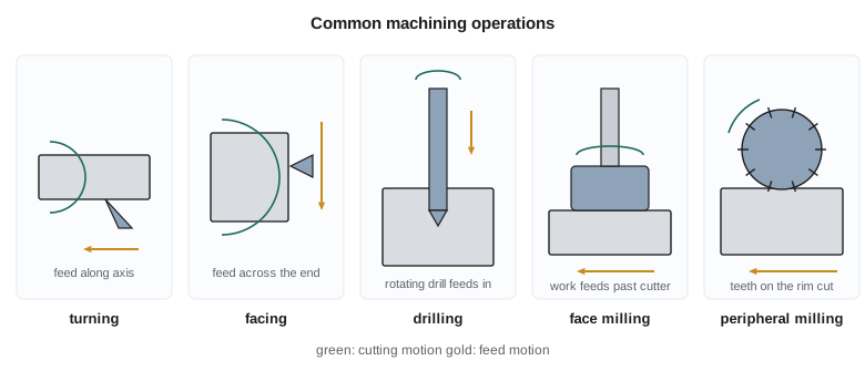
Turning produces surfaces of revolution. The work rotates in a chuck or between centres while a single-point tool moves along it. Straight turning reduces the diameter along the axis; facing moves the tool across the end to make a flat face; taper and contour turning move the tool along a programmed path to produce cones, radii and profiles; grooving and parting plunge a narrow tool radially to cut grooves or cut the part off; threading moves the tool in step with the spindle to cut a helix; and boring enlarges an existing hole with a tool on a bar. Drilling, reaming and tapping on the axis complete the lathe's repertoire.
For a straight turning pass of length \(L\), the cutting time follows from the feed rate in millimetres per minute, \(f_r = fN\), plus a small allowance for approach and overtravel. Because spindle speed is set from the desired cutting speed and the current diameter, \(N = v/(\pi D)\), the time can be written either way.
Milling
Milling uses a rotating cutter with several teeth, while the work feeds past it. It makes flat faces, slots, pockets, steps, contours and, with five-axis machines, complex sculptured surfaces. In peripheral milling, the teeth on the cutter's circumference do the cutting and the cutter axis is parallel to the surface; in face milling, the teeth on the end of a large cutter generate a flat surface perpendicular to the axis. End mills, used on vertical machining centres, cut with both their ends and sides and do most pocketing and profiling work.
Each tooth takes a chip that varies in thickness as it sweeps through the cut, and each tooth cuts only part of the time, which is easier on heat but harder on the edge because of repeated impact. The feed is specified per tooth, \(f_z\), and the table feed rate is \(f_r = f_z\, z\, N\) for a cutter with \(z\) teeth. In up milling, the cutter rotates against the feed, and each chip starts thin and ends thick; in down milling, or climb milling, it rotates with the feed, so each chip starts thick. Climb milling usually gives better finish and tool life on rigid, backlash-free CNC machines.
For the KG-40 housing, the mating face is face milled with a 125 mm cutter carrying eight inserts, and its bolt holes, bearing bores and oil passages are drilled and bored on a horizontal machining centre with a rotary table, so that four faces can be reached in one setup.
Drilling and hole-making
Drilling makes more holes than any other process. A twist drill has two cutting lips at its point and helical flutes that carry chips out. The cutting speed is greatest at the outer corners and falls to zero at the centre, where the chisel edge does not cut so much as push material aside; that is why drill thrust forces are high and why a pilot hole or a split-point drill helps. Hole depths beyond about three diameters need peck drilling, retracting periodically to clear chips, or coolant delivered through the drill. Reaming follows drilling to bring a hole to size and finish with a tolerance of a few hundredths of a millimetre; boring corrects position and straightness. Tapping cuts internal threads, and thread milling, which interpolates a small cutter around the hole, makes them with less risk of a broken tap.
The oil hole in the KG-40 shaft is 4 mm in diameter and crosses a 40 mm journal, a depth of ten diameters, which calls for a through-coolant carbide drill and peck cycles. Its entry is deburred with a small chamfering tool, because burrs inside an oil passage break off later and damage bearings.
Machining time and cost per part
The cost of a machining operation per part has four main pieces: the cost of machine and operator time while cutting, the cost of time spent loading, unloading and idling, the cost of changing tools when they wear out, and the cost of the tools themselves. With a combined machine-and-labour rate \(C_o\) in dollars per minute, handling time \(t_h\), cutting time \(t_m\), tool change time \(t_t\) and cost per cutting edge \(C_t\), and with each edge lasting a tool life \(T\), the cost per part is:
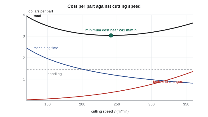
Cutting faster shortens \(t_m\) but shortens \(T\) much more, through Taylor's equation, so tool costs climb. There is a cutting speed that minimizes the total. Substituting \(t_m \propto 1/v\) and \(T = (C/v)^{1/n}\) and setting the derivative to zero gives the tool life and speed for minimum cost. A related optimum, for maximum production rate, ignores costs and minimizes time per part.
Worked problem
Economic cutting speed for the shaft rough turning
Rough turning of the KG-40 shaft takes a total cutting length equivalent to one pass of 300 mm at a mean diameter of 52 mm, with a feed of 0.30 mm/rev. The carbide insert follows the Taylor constants found in Lesson 5, \(n = 0.239\), \(C = 439\ \text{m/min}\). The machine and operator cost 1.80 dollars per minute; changing an insert edge takes 1.5 min; each edge costs 4.20 dollars. Find the speed for minimum cost, the cutting time and the cost per part, excluding handling.
Show solution
- Tool life for minimum cost: \(T = (1/0.239 - 1)(1.5 + 4.20/1.80) = 3.184(3.833) = 12.2\ \text{min}\).
- Speed: \(v = 439/12.2^{0.239} = 439/1.818 = 241\ \text{m/min}\).
- Cutting time: \(t_m = \pi(52)(300)/(0.30 \times 241\,000) = 0.677\ \text{min}\).
- Cost: \(1.80(0.677) + (0.677/12.2)(1.80 \times 1.5 + 4.20) = 1.22 + 0.38 = 1.60\) dollars per part.
Answer: About 240 m/min, giving a 12 minute edge life and about 18 parts per edge. Running at the maximum production speed (T = 4.8 min, about 300 m/min) would save a few seconds per part but cost more in inserts and changes.
# Cost per part against cutting speed: KG-40 shaft rough turning
import math

n, C = 0.239, 439.0          # Taylor constants (m/min) from the Lesson 5 tests
D, L, f = 52.0, 300.0, 0.30  # mm, mm, mm/rev
Co, tt, Ct, th = 1.80, 1.5, 4.20, 0.8   # $/min, min per edge change, $ per edge, handling min

def costs(v):
    tm = math.pi * D * L / (f * v * 1000)       # cutting time, min
    T = (C / v) ** (1 / n)                       # tool life, min
    tool = tm / T * (Co * tt + Ct)
    return tm, T, Co * th, Co * tm, tool

print(" v (m/min)  t_m (min)  T (min)  handling  machining  tools   total ($)")
for v in (150, 180, 210, 241, 270, 300, 340):
    tm, T, h, m, tool = costs(v)
    print(f"{v:10d}  {tm:9.3f}  {T:7.1f}  {h:8.2f}  {m:9.2f}  {tool:5.2f}  {h + m + tool:9.2f}")

T_cost = (1 / n - 1) * (tt + Ct / Co)
T_prod = (1 / n - 1) * tt
for label, T in (("minimum cost", T_cost), ("maximum production", T_prod)):
    v = C / T ** n
    tm = math.pi * D * L / (f * v * 1000)
    print(f"\n{label:18s}: T = {T:5.1f} min, v = {v:5.0f} m/min, "
f"time per part {th + tm + tm / T * tt:.3f} min, parts per edge {T / tm:.0f}") v (m/min) t_m (min) T (min) handling machining tools total ($)
150 1.089 89.4 1.44 1.96 0.08 3.48
180 0.908 41.7 1.44 1.63 0.15 3.22
210 0.778 21.9 1.44 1.40 0.25 3.09
241 0.678 12.3 1.44 1.22 0.38 3.04
270 0.605 7.6 1.44 1.09 0.55 3.08
300 0.545 4.9 1.44 0.98 0.76 3.18
340 0.480 2.9 1.44 0.86 1.14 3.44
minimum cost : T = 12.2 min, v = 241 m/min, time per part 1.560 min, parts per edge 18
maximum production: T = 4.8 min, v = 302 m/min, time per part 1.511 min, parts per edge 9In practice, shops rarely run exactly at the computed optimum. Tool makers' recommended speeds, the need to change tools at convenient times such as shift changes, and the cost curve's flat bottom all leave room for judgment. The calculation is most valuable for showing which way to move: if inserts are cheap and tool changes quick, run faster; if a tool change means stopping a whole cell for ten minutes, run slower and get longer life.
Numerical control
Computer numerical control machines move their axes under the direction of a program. A CNC turning centre has at least two axes, X for diameter and Z along the spindle; a machining centre has three linear axes, X, Y and Z, and often one or two rotary axes for multi-face or five-axis work. Each axis has a servo motor, a ball screw and a feedback device, usually an encoder or a linear scale, that reports the actual position so that the control can correct any error.
Programs are written in a code descended from the 1960s standard often called G-code. Preparatory codes such as G00 (rapid move), G01 (linear feed move), G02 and G03 (circular arcs) and G96 (constant surface speed) set the type of motion; M codes switch the spindle, coolant and tool changer; and words such as X, Z, F and S give positions, feeds and speeds. Canned cycles pack common sequences, such as peck drilling or multi-pass rough turning, into a single line. A turning centre running with G96 adjusts spindle speed continuously as the tool moves to smaller diameters, keeping the cutting speed, and therefore tool life, constant.
# Generate a finishing pass for the 40 mm bearing journal and estimate its cutting time
import math

v, f = 260, 0.12            # finishing: m/min, mm/rev
z_start, z_end = 2.0, -62.0  # mm along the shaft
x_dia = 40.0                 # finished diameter, mm
chamfer = 1.0                # 45 degree chamfer at the shoulder end

lines = [
    "O2101 (KG-40 OUTPUT SHAFT - JOURNAL FINISH)",
    "G21 G18 G40 G99          (metric, XZ plane, no comp, feed per rev)",
    "T0303                    (finishing insert, offset 3)",
    f"G96 S{v} M03             (constant surface speed {v} m/min)",
    "G50 S3500                (spindle limit 3500 rpm)",
    f"G00 X{x_dia - 2*chamfer - 2:.1f} Z{z_start:.1f} M08",
    f"G01 X{x_dia - 2*chamfer:.1f} Z0.0 F{f:.2f}",
    f"G01 X{x_dia:.1f} Z{-chamfer:.1f}",
    f"G01 Z{z_end:.1f}",
    f"G01 X{x_dia + 8:.1f}",
    "G00 X150.0 Z100.0 M09",
    "M30",
]
print("\n".join(lines))

length = abs(z_end - 0.0) + 4      # feed moves along Z plus chamfer and retract, mm
rpm = v * 1000 / (math.pi * x_dia)
t = length / (f * rpm)
print(f"\nSpindle about {rpm:.0f} rpm at 40 mm; feed moves {length:.0f} mm; cutting time {t * 60:.1f} s")O2101 (KG-40 OUTPUT SHAFT - JOURNAL FINISH) G21 G18 G40 G99 (metric, XZ plane, no comp, feed per rev) T0303 (finishing insert, offset 3) G96 S260 M03 (constant surface speed 260 m/min) G50 S3500 (spindle limit 3500 rpm) G00 X36.0 Z2.0 M08 G01 X38.0 Z0.0 F0.12 G01 X40.0 Z-1.0 G01 Z-62.0 G01 X48.0 G00 X150.0 Z100.0 M09 M30 Spindle about 2069 rpm at 40 mm; feed moves 66 mm; cutting time 15.9 s
Almost nobody hand-writes long programs any more. Computer-aided manufacturing software takes the 3D model, lets the programmer choose tools and strategies, generates tool paths, simulates them to check for collisions, and post-processes them into code for a particular machine. Probes in the spindle measure parts and fixtures during the cycle, so the machine can set work offsets automatically and compensate for tool wear. Combined with automatic tool changers, pallet changers and robotic loading, CNC machines can run unattended for hours.
Workholding, accuracy and safety
A part is only as accurate as its fixture. Workholding must locate the part repeatably, using the 3-2-1 principle (three points define a plane, two a line, one a point), and clamp it firmly enough to resist cutting forces without distorting it. Long slender shafts like the KG-40 output shaft deflect under the cutting force and need support from a tailstock centre or a steady rest, otherwise the middle of the shaft is cut oversize. Thermal growth of the spindle and the part, tool deflection and wear, and machine geometry errors all add to the variation, which the quality methods of Lesson 12 track.
Machine tools are dangerous: rotating chucks catch sleeves and hair, chips are hot and razor-sharp, and broken tools or loose parts can be thrown with great force. CNC machines run behind interlocked doors with polycarbonate windows designed to contain ejected parts, and the door interlocks must never be defeated. Operators wear safety glasses, avoid loose clothing and gloves near rotating parts, and use hooks or brushes, never hands, to clear chips.
Common mistakes
MistakeSetting spindle speed without recalculating for the diameter.
InsteadN = v/(πD): a smaller diameter needs a higher speed for the same cutting speed.
MistakeUsing feed per tooth as the table feed rate in milling.
InsteadTable feed f_r = f_z z N.
MistakeChoosing the highest possible cutting speed to save time.
InsteadTool life falls steeply with speed; the minimum-cost speed balances time, tools and tool changes.
MistakeDrilling deep holes in one pass.
InsteadBeyond about 3D, use peck cycles or through-coolant drills to clear chips.
MistakeTurning a long slender shaft without support.
InsteadUse a tailstock or steady rest so deflection does not make the shaft barrel-shaped.
Summary and key terms
- Lathes turn, face, bore, groove, thread and drill; cutting time t_m = πD(L + A)/(fv).
- Milling uses multi-tooth cutters; feed rate f_r = f_z z N; climb milling suits rigid CNC machines.
- Drilling makes most holes; deep holes need pecking or through-coolant; reaming and boring refine size and position.
- Cost per part combines machine time, handling, tool changes and tool cost; T_min cost = (1/n − 1)(t_t + C_t/C_o).
- CNC machines use servo-driven axes with feedback, programmed in G-code usually generated by CAM software.
- Fixtures locate by the 3-2-1 principle; slender work needs support; guards and interlocks protect operators.
- Turning
- Cutting a rotating workpiece with a single-point tool to produce surfaces of revolution.
- Facing
- Turning a flat surface across the end of a workpiece.
- Boring
- Enlarging and truing an existing hole with a single-point tool.
- Face milling
- Milling a flat surface with teeth on the end of a cutter.
- Climb milling
- Milling with the cutter rotating in the direction of feed.
- Reaming
- Finishing a drilled hole to accurate size and smooth finish.
- Minimum-cost speed
- The cutting speed that minimizes total cost per part.
- CNC
- Computer numerical control: automatic control of machine axes by a stored program.
- G-code
- The programming language used to command CNC machine motions.
- CAM
- Computer-aided manufacturing software that generates tool paths from a model.
- 3-2-1 principle
- Locating a part with three, two and one contact points to fix its six degrees of freedom.
Practice problems
Work each problem on paper first, then reveal the answer to check.
Find the time to turn a 40 mm bar over 150 mm at v = 200 m/min, f = 0.2 mm/rev, ignoring approach.
Show answer
t = π(40)(150)/(0.2 × 200 000) = 0.47 min.
A 100 mm, 6-tooth face mill runs at 800 rpm with f_z = 0.15 mm. Find the table feed.
Show answer
f_r = 0.15 × 6 × 800 = 720 mm/min.
For n = 0.25, t_t = 2 min, C_t = 6 dollars and C_o = 1.5 dollars per min, find the tool life for minimum cost.
Show answer
T = 3(2 + 4) = 18 min.
For the same tool, find the tool life for maximum production rate.
Show answer
T = 3(2) = 6 min.
Why does G96 help tool life when facing?
Show answer
It raises spindle speed as the diameter falls, keeping the cutting speed, and thus wear rate, constant.
In the program, double the insert cost to 8.40 dollars. What happens to the minimum-cost speed?
Show answer
T rises to about 19.6 min and v falls to about 216 m/min.
Lesson quiz · 5 questions
Score 60% or more to complete this lesson.
Create a free account to save your progress, take quizzes and earn a certificate.