
MEC-280 · Lesson 11 of 12 · 22 min
Additive manufacturing
When Dev Patel's team needed fixtures to hold the KG-40 housing on the coordinate measuring machine, a set of drill guides for the cross holes, and a prototype breather body to check fit before cutting the injection mould, none of them went to the machine shop. They were printed overnight on the plant's polymer printers. Later in the launch, a bracket for the robot's welding torch that kept cracking was redesigned with lattice ribs and printed in stainless steel by a service bureau. Additive manufacturing, often called 3D printing, builds parts layer by layer directly from a digital model. It has grown from a prototyping curiosity into a set of production processes, and every manufacturing engineer now needs to know when it makes sense and when it does not.
From model to part
Every additive process follows the same digital chain. A 3D CAD model is exported, usually as a triangulated surface mesh or, increasingly, in richer formats that carry colour, material and lattice data. Build preparation software orients the part, adds support structures where needed, and slices the model into layers, typically 0.02 to 0.4 mm thick, generating the path the machine will follow in each layer. After printing, the part goes through post-processing: removing it from the build plate, removing supports, cleaning, curing or heat treating, and often machining critical surfaces. Post-processing is frequently half or more of the total time and cost, a fact that early enthusiasm tended to overlook.
Building in layers has consequences. Sloped and curved surfaces show a staircase effect, with a step height equal to the layer thickness; finer layers reduce it but lengthen the build. Properties are often weaker between layers than within them, so orientation affects strength. Overhangs beyond about 45° from vertical usually need supports, which cost material and time and leave marks when removed. Designers learn to orient parts to minimize supports on critical surfaces and to keep important loads in the strong directions.
The process families
An international standard groups additive processes into seven families, and the names are worth knowing because they describe how each one works.
| Family | How it works | Typical materials | Typical uses |
|---|---|---|---|
| Material extrusion | Heated nozzle deposits a bead of molten filament | PLA, ABS, nylon, PETG, carbon-filled polymers | Fixtures, prototypes, jigs |
| Vat photopolymerization | Light cures liquid resin layer by layer | Photopolymer resins | Detailed prototypes, dental models, casting patterns |
| Powder bed fusion | Laser or electron beam fuses powder layer by layer | Nylon 12, titanium, stainless steel, Inconel, aluminum | Functional polymer parts, aerospace and medical metal parts |
| Material jetting | Print heads jet droplets of photopolymer cured by UV | Photopolymers, multiple colours | Visual prototypes, multi-material models |
| Binder jetting | Print heads jet binder onto powder; part sintered later | Sand, stainless steel, ceramics | Sand moulds and cores, volume metal parts |
| Directed energy deposition | Laser or arc melts wire or powder fed into the pool | Titanium, steels, nickel alloys | Large parts, repair, adding features |
| Sheet lamination | Sheets bonded and cut layer by layer | Paper, metal foil | Low-cost models, embedded sensors |
Material extrusion and vat photopolymerization
Material extrusion, often known by a trade name for fused filament fabrication, is the most familiar process: a heated nozzle traces each layer with a bead of molten thermoplastic. Machines range from desktop printers to large-format systems. Parts are relatively coarse and anisotropic, but materials are cheap, the machines are simple and reinforced filaments with chopped carbon fibre give stiff, useful fixtures. The KG-40 measuring fixtures are printed in carbon-filled nylon at 0.2 mm layers with 40 percent infill, enough stiffness for gauging at a fraction of the cost and lead time of machined aluminum fixtures.
Vat photopolymerization cures a liquid resin with ultraviolet light, either tracing each layer with a laser (stereolithography) or projecting a whole layer at once from a digital light projector or masked LCD screen. It gives fine detail and smooth surfaces, ideal for prototypes, dental aligner moulds and investment casting patterns. Resins can be brittle and may degrade with UV and heat, though engineering resins have improved greatly.
Metal powder bed fusion
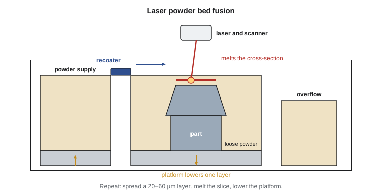
Laser powder bed fusion is the leading process for metal parts. A recoater spreads a powder layer 20 to 60 µm thick over the build plate, inside a chamber filled with argon or nitrogen. One or more lasers, each a few hundred watts, scan the cross-section, melting the powder into tiny tracks that solidify within milliseconds. The plate lowers, a new layer is spread, and the process repeats thousands of times. Electron beam melting works similarly in vacuum with a preheated bed, giving lower residual stress in titanium parts.
The extremely fast cooling gives fine microstructures and good strength, often matching or exceeding cast and wrought properties after heat treatment. The steep thermal gradients also build up large residual stresses, which can warp parts or crack them off their supports, so parts are usually stress relieved before removal from the plate. Porosity from lack of fusion or trapped gas, rough as-built surfaces (Ra 6 to 20 µm) and anisotropy must be managed. Critical parts are often hot isostatically pressed, held at high temperature and gas pressure to close internal pores, and then machined on functional surfaces.
Build time depends on the volume melted and on the number of layers, since each recoat takes several seconds whether the layer contains a tiny section or a large one. Tall parts are therefore slow even if they are small in volume, and machines are filled with as many parts as will fit to share the recoating time.
Worked problem
Printing or machining the torch bracket
The redesigned stainless steel torch bracket has a volume of 38 cm³ and supports of 9 cm³, and stands 85 mm tall. The service bureau's machine melts 12 cm³/h with one laser at 40 µm layers, with 8 s per recoat. Machine time costs 95 dollars per hour, powder 0.35 dollars per cubic centimetre including losses, and post-processing (stress relief, removal, support removal, bead blasting, machining two holes) 60 dollars. Estimate the build time and cost of one bracket if built alone, and per bracket if eight are built together.
Show solution
- Layers: \(85/0.040 = 2125\); recoat time \(= 2125 \times 8/3600 = 4.7\ \text{h}\).
- Melting time for one: \(47/12 = 3.9\ \text{h}\); total \(8.6\ \text{h}\), machine cost 821 dollars, plus powder 16 dollars and post-processing 60 dollars: about 897 dollars.
- Eight together: melting \(8 \times 3.9 = 31.3\ \text{h}\), recoat still 4.7 h, total 36.1 h, machine cost 3426 dollars or 428 dollars each.
- Per bracket with eight: \(428 + 16 + 60 \approx 505\) dollars.
Answer: Batching the build nearly halves the cost per bracket because the recoating time is shared. A machined bracket would cost less, about 160 dollars, but could not include the internal lattice and cooling channel that solved the cracking problem. Printing is justified by the design, not by the cost of making a simple shape.
# Powder bed fusion build time and cost for the stainless torch bracket
import math

V_part, V_supp, height = 38.0, 9.0, 85.0      # cm^3, cm^3, mm
melt_rate = 12.0                               # cm^3 per hour (one laser)
layer, recoat = 0.040, 8.0                     # mm, s per layer
rate, powder, post = 95.0, 0.35, 60.0          # $/h machine, $/cm^3 powder, $ post-processing per part
machined = 160.0                               # $ for a conventionally machined bracket (no lattice)

def per_part(batch, melt=melt_rate):
    layers = math.ceil(height / layer)
    t_recoat = layers * recoat / 3600
    t_melt = batch * (V_part + V_supp) / melt
    t_total = t_melt + t_recoat
    cost = (t_total * rate) / batch + (V_part + V_supp) * powder + post
    return layers, t_total, cost

print("Batch  build time (h)  cost per bracket ($)")
for b in (1, 2, 4, 8, 12):
    layers, t, c = per_part(b)
    print(f"{b:5d}  {t:14.1f}  {c:20.0f}")
print(f"(layers per build: {layers}; machined bracket for comparison: {machined:.0f} $)")

layers, t, c = per_part(8, melt=24.0)
print(f"\nTwo lasers (24 cm^3/h), batch of 8: {t:.1f} h, {c:.0f} $ per bracket")

print("\nLayer thickness (mm)  layers  recoat time (h)")
for lt in (0.02, 0.03, 0.04, 0.06):
    n = math.ceil(height / lt)
print(f"{lt:20.2f} {n:6d} {n * recoat / 3600:15.1f}")Batch build time (h) cost per bracket ($)
1 8.6 897
2 12.6 673
4 20.4 561
8 36.1 505
12 51.7 486
(layers per build: 2125; machined bracket for comparison: 160 $)
Two lasers (24 cm^3/h), batch of 8: 20.4 h, 319 $ per bracket
Layer thickness (mm) layers recoat time (h)
0.02 4250 9.4
0.03 2834 6.3
0.04 2125 4.7
0.06 1417 3.1Binder jetting and directed energy deposition
Binder jetting spreads powder like powder bed fusion but, instead of melting it, jets a liquid binder to glue each cross-section. The fragile green part is cured, removed from the loose powder and then sintered in a furnace, where it shrinks by 15 to 20 percent as it densifies. Because no laser is involved, binder jetting is much faster and suits higher-volume metal parts, though shrinkage must be predicted carefully. Binder-jetted sand is already a production process in foundries: printed sand moulds and cores allow complex castings without patterns. The KG-40 housing's first prototype castings were poured into printed sand moulds, weeks before the production pattern was finished.
Directed energy deposition melts wire or powder fed into a focused laser, electron beam or welding arc, building material bead by bead on a substrate. It can build large parts quickly, add features to existing parts and repair worn or damaged components such as turbine blades, moulds and shafts. Wire-arc additive manufacturing, using robotic arc welding, can build metre-scale parts at several kilograms per hour, finished by machining. Hybrid machines combine deposition and milling in one setup.
Designing for additive manufacturing
Additive processes reward designs that conventional processes cannot make. Lattices and gyroid infills give stiffness with little material. Topology optimization software removes material wherever stress is low, producing organic shapes that use material efficiently. Internal channels can follow any path, giving conformal cooling in mould inserts and the cooling passage in the torch bracket. Several parts of an assembly can be consolidated into one printed part, removing fasteners and joints. At the same time, designers must respect the processes' rules: minimum wall thicknesses, maximum unsupported overhangs, escape holes for trapped powder or resin, allowance for machining stock on precision surfaces and orientation for strength.
When additive makes sense
Additive manufacturing is rarely the cheapest way to make a simple part in quantity. It makes sense when the part is complex enough that conventional processes struggle, when quantities are small so tooling cannot be amortized, when lead time matters more than unit cost, when consolidation or lightweighting pays off over the product's life, or when customization is the point, as for dental aligners, hearing aids and orthopaedic implants matched to each patient. Spare parts on demand, especially for old equipment whose tooling has been lost, are a growing use. For Kestrel Drive Systems, the payoff is clearest in tooling: fixtures, gauges, drill guides, robot grippers and printed sand cores have cut weeks from the KG-40 launch.
Quality assurance for printed production parts is still maturing. Properties depend on machine, parameters, powder condition, orientation and post-processing, so production parts need qualified processes, test specimens printed with each build, and inspection by X-ray computed tomography where internal defects matter. Fine metal powders are also a safety concern: they can be inhaled, and some, such as aluminum and titanium, can ignite or explode as dust clouds, so powder handling needs inert gas, grounding, dust control and protective equipment.
Common mistakes
MistakeIgnoring post-processing in AM cost and time estimates.
InsteadSupport removal, heat treatment, machining and inspection are often half the total.
MistakeAssuming printed parts have uniform properties in all directions.
InsteadLayer bonding and anisotropy make orientation matter; test specimens in the build directions.
MistakeBuilding one tall part alone in a powder bed machine.
InsteadRecoat time depends on height; batch parts to share it.
MistakeChoosing AM for a simple part at high volume because it needs no tooling.
InsteadCompare total cost; moulding, casting or machining usually win for simple parts in quantity.
MistakeHandling metal powder like ordinary dust.
InsteadFine metal powders are inhalation and explosion hazards; use inert handling, grounding and PPE.
Summary and key terms
- AM builds parts layer by layer from a sliced digital model; post-processing is a major share of time and cost.
- Layers cause stair-stepping, anisotropy and support needs; orientation is a key design choice.
- The seven families are material extrusion, vat photopolymerization, powder bed fusion, material jetting, binder jetting, directed energy deposition and sheet lamination.
- Metal powder bed fusion gives fine microstructures but residual stress, porosity and rough surfaces; HIP and machining follow.
- Build time depends on volume melted and on layer count; batching shares recoat time.
- AM pays where complexity, low volume, lead time, consolidation or customization outweigh unit cost.
- Additive manufacturing
- Building parts by adding material layer by layer from a digital model.
- Slicing
- Dividing a 3D model into layers and generating the tool path for each.
- Staircase effect
- Steps on sloped surfaces caused by finite layer thickness.
- Support structure
- Sacrificial material that holds overhangs during printing.
- Powder bed fusion
- Selectively melting layers of powder with a laser or electron beam.
- Vat photopolymerization
- Curing liquid resin layer by layer with light.
- Binder jetting
- Jetting binder onto powder layers, then sintering the part.
- Directed energy deposition
- Melting fed wire or powder with a focused energy source to build or repair parts.
- Hot isostatic pressing
- Heating under high gas pressure to close internal porosity.
- Topology optimization
- Computational removal of material where it carries little load.
- Part consolidation
- Replacing an assembly of several parts with a single printed part.
Practice problems
Work each problem on paper first, then reveal the answer to check.
How many layers are needed to print a 60 mm tall part at 0.05 mm layers?
Show answer
1200 layers.
A desktop printer deposits 15 cm³/h. How long does a 90 cm³ fixture take, ignoring travel moves?
Show answer
About 6 h.
Why does a powder bed machine print eight short parts not much more slowly than one tall part of the same total volume?
Show answer
Recoat time depends on height (layer count), not on how many parts share each layer.
Name two reasons metal PBF parts are often hot isostatically pressed.
Show answer
To close internal porosity and improve fatigue properties (and homogenize the microstructure).
Give two cases where AM beats machining despite higher unit cost.
Show answer
Complex internal features, very low quantities, urgent lead times, part consolidation or customized parts.
In the program, raise the melt rate to 24 cm³/h with two lasers. What is the cost per bracket in a batch of eight?
Show answer
About 319 dollars.
Lesson quiz · 5 questions
Score 60% or more to complete this lesson.
Create a free account to save your progress, take quizzes and earn a certificate.