
MEC-270 · Lesson 9 of 12 · 23 min
Linear momentum: forces on bends, nozzles and jets
Where the 600 mm transmission main turns 90° at the foot of the reservoir ridge, a massive concrete anchor block surrounds the bend. Jun Park asked why a slow-moving water main needs so much concrete. The answer comes from Newton's second law applied to a control volume: whenever a flow changes direction or speed, or the pressure in it acts on a changing area, the pipe must push on the water, and the water pushes back on the pipe. Without the anchor block, the bend would be shoved off its joints the first time the main was pressurized. This lesson develops the linear momentum equation and applies it to bends, reducers, nozzles and jets.
The momentum equation for a control volume
For a system, Newton's second law says that the net force equals the rate of change of momentum. Moving to a fixed control volume with the Reynolds transport theorem, as we did for mass in Lesson 6, gives the linear momentum equation. The net force on the fluid inside the control volume equals the rate of increase of momentum inside plus the net rate at which momentum flows out across the control surface.
For steady flow with uniform velocities at each inlet and outlet, the first term vanishes, and for a single inlet and outlet the equation reduces to \(\sum \mathbf{F} = \dot{m}(\mathbf{V}_2 - \mathbf{V}_1)\). It is a vector equation, applied separately in each coordinate direction, and the velocities are vectors: a flow that turns without changing speed still changes its momentum.
The forces on the fluid in the control volume are of three kinds. Pressure forces act on every part of the control surface where fluid crosses it; at an inlet or outlet of a pipe, this is the pressure times the area, pushing inward. Body forces, mainly gravity, act on the mass inside. And the solid boundaries, such as the pipe wall and the bend, exert a force on the fluid, which is usually the unknown we want. The force on the pipe from the water is equal and opposite.
Choosing the control volume and using gauge pressure
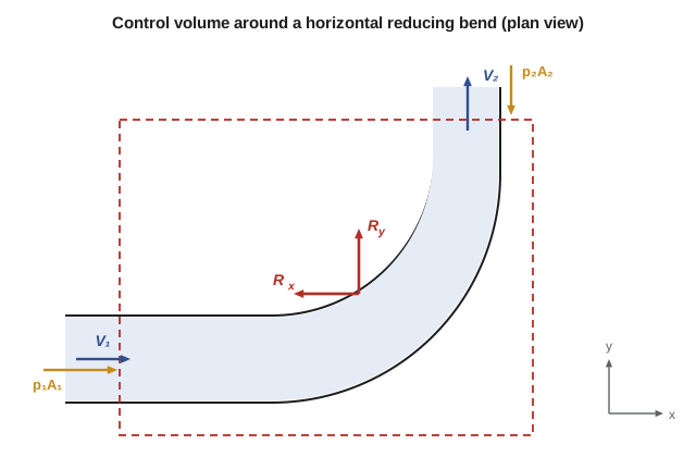
Good control volumes cut across inlets and outlets perpendicular to the flow, where velocity and pressure are known, and enclose the object whose force we want. Draw the control volume, mark the coordinate axes, and draw every force: pressure forces at each cut, the weight if gravity has a component along an axis, and the unknown reaction force from the solid. Then write the momentum equation in each direction, taking care that each velocity component has the right sign.
Atmospheric pressure acts all around the outside of a pipe and the anchor block. If we used absolute pressure at the inlet and outlet cuts, we would also have to include atmospheric pressure acting on the outside surfaces. Since a uniform pressure over a closed surface exerts no net force, it is simpler to use gauge pressures at the cuts and ignore atmospheric pressure entirely. The result is the force the anchor must provide beyond what the surrounding air already balances.
Worked problem
Anchor force on a 90° reducing bend
A horizontal 90° bend reduces the main from 600 mm to 500 mm. It carries 0.45 m³/s of water, and the gauge pressure at the inlet is 520 kPa. Neglecting losses across the bend, find the force the anchor block must exert on the bend. Take the inlet flow along +x and the outlet flow along +y.
Show solution
- Velocities: \(A_1 = 0.2827\ \text{m}^2\), \(V_1 = 1.59\ \text{m/s}\); \(A_2 = 0.1963\ \text{m}^2\), \(V_2 = 2.29\ \text{m/s}\). Mass flow \(\dot{m} = 998(0.45) = 449\ \text{kg/s}\).
- Outlet pressure from Bernoulli: \(p_2 = 520\,000 + 998(1.59^2 - 2.29^2)/2 = 518\,600\ \text{Pa}\).
- x direction: \(R_x + p_1A_1 = \dot{m}(0 - V_1)\), so \(R_x = -449(1.59) - 520\,000(0.2827) = -147.7\ \text{kN}\).
- y direction: \(R_y - p_2A_2 = \dot{m}(V_2 - 0)\), so \(R_y = 449(2.29) + 518\,600(0.1963) = 102.9\ \text{kN}\).
- Magnitude \(R = \sqrt{147.7^2 + 102.9^2} = 180\ \text{kN}\).
Answer: The anchor must push back toward the inlet and toward the outlet direction with a total of 180 kN, about the weight of 18 tonnes. Almost all of it comes from pressure: the momentum terms contribute less than 2 kN. That is why anchor blocks are designed for the test pressure, which is often 1.5 times the working pressure.
The program below repeats the calculation for 45° and 90° bends and separates the pressure and momentum contributions. In water mains, pressure dominates; the momentum terms matter more in high-velocity jets and in low-pressure, high-velocity flows such as fan ducts. A bend in a gravity sewer, flowing at low pressure, needs little thrust restraint, while the same bend in a pressurized force main needs a block.
# Linear momentum: anchor force on a reducing bend and force of a jet on a plate
import math
rho = 998.0

def bend_force(Q, D1, D2, p1g, p2g, theta_deg, W=0.0):
    """Force the anchor block must exert on a horizontal-plane reducing bend (x along the inlet)."""
    A1, A2 = math.pi * D1**2 / 4, math.pi * D2**2 / 4
    V1, V2 = Q / A1, Q / A2
    th = math.radians(theta_deg)
    mdot = rho * Q
    # sum F = mdot (V_out - V_in), pressures in gauge
    Rx = mdot * (V2 * math.cos(th) - V1) - p1g * A1 + p2g * A2 * math.cos(th)
    Ry = mdot * (V2 * math.sin(th)) + p2g * A2 * math.sin(th)
    return Rx, Ry, V1, V2

Q = 0.45
p1 = 520e3                                 # Pa gauge upstream
D1, D2 = 0.600, 0.500
V1, V2 = Q / (math.pi * D1**2 / 4), Q / (math.pi * D2**2 / 4)
p2 = p1 + rho * (V1**2 - V2**2) / 2        # Bernoulli across the bend, losses neglected
for th in (45, 90):
    Rx, Ry, V1, V2 = bend_force(Q, D1, D2, p1, p2, th)
    R = math.hypot(Rx, Ry)
    print(f"{th:3d} deg bend: V1 = {V1:.2f}, V2 = {V2:.2f} m/s, Rx = {Rx/1000:7.1f} kN, Ry = {Ry/1000:6.1f} kN, |R| = {R/1000:6.1f} kN")

# How much of the 90-degree anchor force comes from pressure?
A1, A2 = math.pi * D1**2 / 4, math.pi * D2**2 / 4
print(f"Pressure part of Rx: {-p1*A1/1000:.1f} kN; momentum part: {-rho*Q*V1/1000:.2f} kN")

# Water jet from a fire monitor striking a flat plate normally
d, Vj = 0.040, 30.0
Qj = math.pi * d**2 / 4 * Vj
print(f"Jet force on a fixed plate: {rho*Qj*Vj:.0f} N; on a plate moving away at 10 m/s: {rho*math.pi*d**2/4*(Vj-10)**2:.0f} N")45 deg bend: V1 = 1.59, V2 = 2.29 m/s, Rx = -75.0 kN, Ry = 72.7 kN, |R| = 104.5 kN 90 deg bend: V1 = 1.59, V2 = 2.29 m/s, Rx = -147.7 kN, Ry = 102.9 kN, |R| = 180.0 kN Pressure part of Rx: -147.0 kN; momentum part: -0.71 kN Jet force on a fixed plate: 1129 N; on a plate moving away at 10 m/s: 502 N
Thrust restraint in practice
Unbalanced forces occur at every bend, tee, reducer, dead end and closed valve in a pressurized pipeline. Pipes with push-on or mechanical joints cannot carry tension across the joints, so the force must be transferred to the soil. Concrete thrust blocks bear against undisturbed soil behind the fitting; their bearing area is the thrust divided by the soil's allowable bearing pressure, which might be 75 to 200 kPa. Where space or soil is poor, restrained joints lock several lengths of pipe together so friction along the pipe and soil resistance carry the thrust instead. A dead end, such as a capped main awaiting extension, sees the full \(pA\) as thrust, which for a 600 mm main at 520 kPa is 147 kN.
Vertical bends add another twist. At a bend that turns upward, the thrust pushes down into the soil and is easily resisted; at a bend that turns downward over a hump, the thrust pulls up, and the block must be heavy enough to hold the bend down by its weight. Hana's crews learned this the hard way when a poorly anchored vertical bend lifted during a pressure test and split its joint.
Nozzles and jets
A nozzle accelerates water, so it needs an axial force to hold it on its pipe. For a fire hose nozzle reducing a 65 mm hose to a 25 mm tip, the jet leaves at high speed and the pressure inside the hose is large; the coupling must hold back the pressure force on the hose area minus the momentum gained. Firefighters feel the reaction of the jet as a push back along the hose, roughly \(\rho Q V_{\text{jet}}\), which for a large handline can exceed 300 N.
A free jet striking a surface exerts a force equal to the rate at which its momentum is changed. A jet hitting a fixed flat plate square-on and spreading sideways loses all its momentum in the original direction, so the force is \(\rho Q V\). If the plate moves away at speed \(u\), the jet strikes it at the relative velocity \(V - u\), and the mass flow reaching the plate is also reduced, so the force becomes \(\rho A (V - u)^2\). A jet turned back on itself by a curved vane changes its momentum by nearly twice as much, which is the principle of the Pelton turbine, whose buckets turn the jet through almost 180°.
Worked problem
Jet from a hydrant test nozzle
During a hydrant flow test, a 40 mm jet leaves a nozzle at 30 m/s and strikes a fixed flat plate square-on. Find the force on the plate, and the force if the plate moved away from the nozzle at 10 m/s.
Show solution
- Jet area \(A = \pi(0.040)^2/4 = 1.257 \times 10^{-3}\ \text{m}^2\); \(Q = AV = 0.0377\ \text{m}^3/\text{s}\).
- Fixed plate: \(F = \rho Q V = 998(0.0377)(30) = 1129\ \text{N}\).
- Moving plate: \(F = \rho A(V - u)^2 = 998(1.257 \times 10^{-3})(20)^2 = 502\ \text{N}\).
Answer: The fixed plate feels about 1.13 kN. Moving away at a third of the jet speed cuts the force by more than half, because both the relative velocity and the mass flow reaching the plate fall.
Momentum flux correction and the limits of the method
Using the average velocity to compute momentum flux slightly underestimates it, because the velocity varies across the pipe and momentum depends on velocity squared. A momentum flux correction factor \(\beta\) fixes this: about 1.02 to 1.04 for turbulent pipe flow and 4/3 for laminar flow. For most water main calculations the correction is far smaller than the uncertainty in pressure, and it is set to 1.
The momentum equation gives forces from what crosses the control surface, without our needing to know the complicated flow inside. That is its great strength. It cannot by itself give the pressure distribution inside a fitting, and when losses are significant, the outlet pressure must come from the energy equation with a loss term, not from Bernoulli. The anchor block example used Bernoulli for the outlet pressure because the bend is short and smooth; for a sharp-cornered fitting, a measured loss coefficient should be used instead, as Lesson 12 explains.
Common mistakes
MistakeUsing absolute pressures at the cuts and forgetting atmospheric pressure on the outside.
InsteadUse gauge pressures at the cuts; uniform atmospheric pressure over a closed surface exerts no net force.
MistakeTreating velocity as a scalar.
InsteadMomentum is a vector; a flow that turns at constant speed still changes momentum.
MistakeGetting the direction of pressure forces at the cuts wrong.
InsteadPressure at an inlet or outlet always pushes into the control volume.
MistakeReporting the force on the fluid as the force on the pipe.
InsteadThe force on the pipe is equal and opposite to the force on the fluid.
MistakeDesigning a thrust block for working pressure only.
InsteadUse the test or surge pressure, which is higher.
Summary and key terms
- For steady flow, ΣF = Σṁ V_out − Σṁ V_in, applied as a vector equation in each direction.
- Forces on the control volume include pressure at the cuts, gravity and the reaction from solid boundaries.
- Use gauge pressure at the cuts; atmospheric pressure cancels around a closed surface.
- In water mains, pressure forces dominate the thrust at bends, tees, reducers and dead ends.
- A jet striking a fixed plate square-on exerts F = ρQV; a moving plate feels ρA(V − u)².
- Thrust blocks and restrained joints transfer pipeline thrust to the soil.
- Linear momentum equation
- Newton's second law for a control volume: net force equals the net momentum outflow rate plus the rate of change inside.
- Momentum flux
- The rate at which momentum crosses a surface, ṁV for uniform flow.
- Reaction force
- The force a solid boundary exerts on the fluid in a control volume.
- Thrust block
- A concrete mass that transfers the thrust at a pipe fitting to undisturbed soil.
- Restrained joint
- A pipe joint that can carry axial tension, used to resist thrust by friction along the pipe.
- Free jet
- A stream of fluid surrounded by atmosphere, at atmospheric pressure throughout.
- Momentum flux correction factor
- A factor β correcting momentum flux for a non-uniform velocity profile.
- Pelton turbine
- An impulse turbine whose buckets turn water jets through nearly 180°.
Practice problems
Work each problem on paper first, then reveal the answer to check.
A 300 mm dead end on a main at 600 kPa: what thrust must the cap resist?
Show answer
F = pA = 600 000(0.0707) = 42.4 kN.
A horizontal 90° bend of constant diameter 400 mm carries 0.25 m³/s at 400 kPa. Find the magnitude of the anchor force, neglecting losses.
Show answer
V = 1.99 m/s; each component = pA + ṁV = 50.3 + 0.50 = 50.8 kN; R = 71.8 kN.
A 25 mm jet at 35 m/s strikes a fixed plate square-on. Find the force.
Show answer
Q = 0.0172 m³/s; F = 998(0.0172)(35) = 600 N.
What soil bearing area does a block need to resist 180 kN where the allowable bearing pressure is 150 kPa?
Show answer
A = 180/150 = 1.2 m².
Why do gravity sewers seldom need thrust blocks at bends?
Show answer
Their internal pressure is near atmospheric, so the pressure forces, which dominate thrust, are small.
In the program, raise the inlet pressure to 780 kPa. What is the 90° anchor force?
Show answer
About 270 kN; the force rises almost in proportion to pressure.
Lesson quiz · 5 questions
Score 60% or more to complete this lesson.
Create a free account to save your progress, take quizzes and earn a certificate.