
ELE-240 · Lesson 5 of 12 · 25 min
LEDs, photodiodes and special-purpose diodes
A pn junction can do more than rectify. When electrons and holes recombine across the band gap, some materials give off the energy as light, and when light is absorbed near a junction, it creates electron–hole pairs that become a current. These two effects, running in opposite directions, give us light-emitting diodes, laser diodes, photodiodes and solar cells. Varying the junction's construction gives still other devices: Schottky diodes for fast, low-loss rectification and varactors whose capacitance is tuned by voltage. This lesson surveys the special-purpose diodes an electrical engineer meets most often and shows how to design with them.
Light is central to the pedestrian controller. The walk and don't-walk symbols in the signal heads are arrays of LEDs, the cabinet's push-button inputs are isolated through optocouplers, and an ambient-light sensor lets the controller dim the signals at night, as many agencies require to reduce glare. Amara is responsible for the LED drive and the optical inputs.
How an LED makes light
In silicon, recombination releases energy mostly as heat, because silicon has an indirect band gap: an electron at the bottom of the conduction band cannot drop straight into a hole at the top of the valence band without also giving momentum to the crystal. Compound semiconductors such as gallium arsenide, gallium phosphide and gallium nitride have direct band gaps, where that transition happens readily and releases a photon. The photon's energy is close to the band gap, which sets its wavelength:
A band gap of 1.9 eV gives red light near 650 nm; about 2.1 eV gives amber and yellow; about 2.6 to 2.8 eV, from indium gallium nitride, gives blue. White LEDs are usually blue LEDs coated with a phosphor that converts part of the blue into yellow, which the eye sees as white. Because the photon energy is about the band gap energy, the forward voltage is too: red LEDs drop roughly 1.8 to 2.2 V, amber about 2.0 to 2.4 V, and blue, green and white about 2.7 to 3.4 V at their rated current.
| Colour | Typical material | Wavelength | Typical V_F at rated current |
|---|---|---|---|
| Infrared | GaAs, AlGaAs | 850 to 940 nm | 1.2 to 1.6 V |
| Red | AlGaInP | 620 to 650 nm | 1.8 to 2.2 V |
| Amber / yellow | AlGaInP | 590 to 600 nm | 2.0 to 2.4 V |
| Green | InGaN | 520 to 530 nm | 2.8 to 3.4 V |
| Blue | InGaN | 450 to 470 nm | 2.8 to 3.4 V |
| White | InGaN + phosphor | broad | 2.8 to 3.4 V |
Pedestrian signals in North America use a lunar white or white walking person and a Portland orange hand, colours set out in the traffic signal standards adopted by each jurisdiction. The orange hand uses amber-orange AlGaInP LEDs, and the walking person uses white InGaN LEDs, so the two symbols need different drive voltages.
Driving an LED
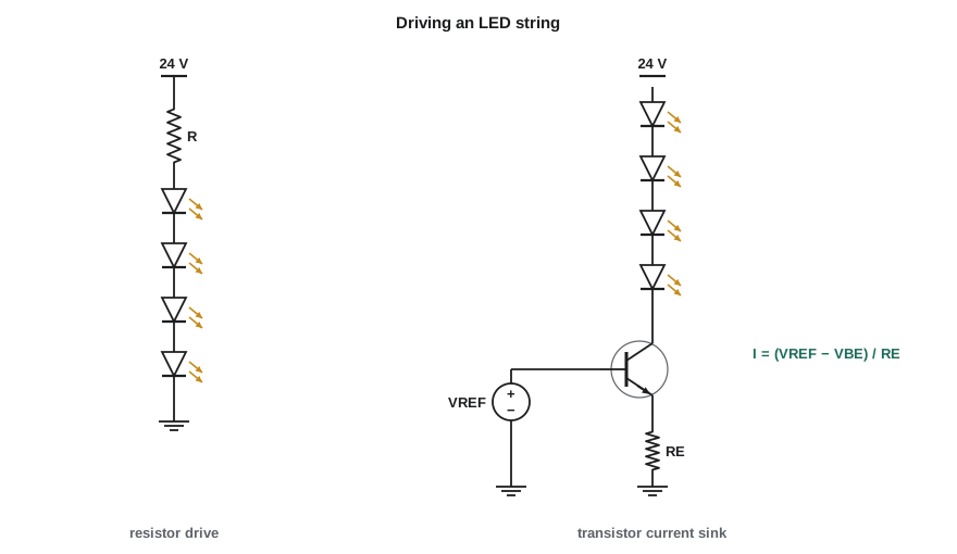
An LED is a diode, so its current rises exponentially with voltage. Applying a fixed voltage directly is a recipe for burnt parts: a small change in temperature or a part-to-part spread in V_F would cause a large change in current. LEDs must be driven by a current, set either by a series resistor from a voltage supply or by an active current source. The light output is roughly proportional to current over the useful range, so the current is what the designer chooses.
Here N LEDs are in series and I_F is the desired current. Putting several LEDs in series uses the supply voltage efficiently, because less is wasted in the resistor, but leaves less headroom for supply variation. A good rule is to keep at least 15 to 25 percent of the supply across the resistor, so the current stays reasonably steady as the supply and V_F vary. Strings are paralleled to make larger arrays, each with its own resistor; parallel LEDs sharing one resistor will not share current evenly, because their forward voltages differ.
Worked problem
A white LED string for the walking-person symbol
The walking-person symbol uses white LEDs rated at 20 mA with V_F between 2.9 and 3.3 V. The unregulated rail is nominally 22.4 V but falls to 17.6 V at low line and rises to 26 V at high line with a light load. How many LEDs per string, and what resistor?
Show solution
- At low line, the string plus resistor must still pass a reasonable current. Try N = 5 at the worst-case (highest) V_F.
- \[5 \times 3.3 = 16.5\ \text{V} \quad\Rightarrow\quad 17.6 - 16.5 = 1.1\ \text{V left for the resistor}\]
- That is too little headroom. Try N = 4.
- \[4 \times 3.3 = 13.2\ \text{V}; \quad R = \frac{22.4 - 4 \times 3.1}{0.020} = \frac{10.0}{0.020} = 500\ \Omega \to 510\ \Omega\]
- \[I_{min} = \frac{17.6 - 13.2}{510} \approx 8.6\ \text{mA}, \quad I_{max} = \frac{26 - 4 \times 2.9}{510} \approx 28\ \text{mA}\]
Answer: Four LEDs per string with 510 Ω gives 20 mA at nominal, but the current ranges from about 8.6 to 28 mA across line and part variation, a brightness change of more than three to one and an overcurrent at high line. A resistor drive is too crude for a signal head that must meet a minimum brightness; Amara will use an active current sink, as in the right half of the figure, which lesson 7 designs.
Heat is the main enemy of LEDs. Light output falls and V_F drops as the junction warms, and life shortens sharply above the rated junction temperature. LED datasheets give derating curves for current versus ambient temperature, and signal heads in direct summer sun can get very hot. Traffic signal modules are therefore usually designed with constant-current drivers, temperature compensation and careful thermal paths.
Photodiodes
When a photon with energy above the band gap is absorbed in or near the depletion region of a junction, it creates an electron–hole pair, and the junction's field sweeps the electron to the n side and the hole to the p side. The result is a photocurrent I_ph flowing in the reverse direction, proportional to the light power. The ratio is the responsivity, R_λ, in amperes per watt; for silicon photodiodes it peaks at about 0.5 to 0.6 A/W near 850 to 950 nm. Silicon responds from about 400 to 1,100 nm, beyond which photons have too little energy to cross the 1.12 eV gap.
A photodiode can be used in two modes. In photoconductive mode it is reverse biased, so the depletion region is wide and its capacitance small, which makes it fast; the current is I_ph plus a small dark current. In photovoltaic mode it has no bias, which eliminates dark current and gives the lowest noise, but it is slower. Either way, the photocurrent is usually tiny, nanoamps to microamps, and is converted to a voltage by a transimpedance amplifier: an op amp from ELE-202 with the photodiode at its inverting input and a feedback resistor R_f, giving v_O = I_ph R_f.
Worked problem
The ambient-light sensor
A silicon photodiode with an effective responsivity of 0.3 A/W over daylight wavelengths receives 2 µW of light in bright daylight and 2 nW at night. A transimpedance amplifier with R_f = 1 MΩ converts its current to a voltage. Find the output in each case.
Show solution
- \[I_{day} = 0.3 \times 2 \times 10^{-6} = 0.6\ \mu\text{A} \quad\Rightarrow\quad v_O = 0.6\ \mu\text{A} \times 1\ \text{M}\Omega = 0.6\ \text{V}\]
- \[I_{night} = 0.3 \times 2 \times 10^{-9} = 0.6\ \text{nA} \quad\Rightarrow\quad v_O = 0.6\ \text{mV}\]
Answer: The output spans 0.6 V to 0.6 mV, a thousand-to-one range. A logarithmic amplifier or a microcontroller reading with automatic range switching handles the span; for a simple day–night switch, a comparator with hysteresis set near 50 mV is enough.
Solar cells
A solar cell is a large-area photodiode used in photovoltaic mode to deliver power. With no load, light raises its voltage to the open-circuit voltage V_OC, about 0.6 to 0.7 V for silicon; short-circuited, it delivers the short-circuit current I_SC, proportional to sunlight. Power is the product of current and voltage, which is zero at both ends of the curve and has a maximum in between, the maximum power point. Practical panels connect dozens of cells in series, and solar chargers track the maximum power point electronically. Some remote pedestrian signals and school-zone flashers run on solar panels and batteries for this reason.
import math
VT, n = 0.02585, 1.3
Isc, Is = 3.0, 1.0e-8        # one cell in full sun: 3 A short-circuit current
best = (0, 0, 0)
for k in range(0, 701):
    v = k / 1000
    i = Isc - Is * (math.exp(v / (n * VT)) - 1)
    if i < 0: break
    p = v * i
    if p > best[0]: best = (p, v, i)
Voc = n * VT * math.log(Isc / Is + 1)
p, vm, im = best
print(f"Voc = {Voc:.3f} V, Isc = {Isc:.1f} A")
print(f"maximum power {p:.2f} W at {vm:.3f} V and {im:.2f} A")
print(f"fill factor = {p / (Voc * Isc):.2f}")
print(f"36 cells in series: about {36 * vm:.1f} V at the maximum power point")Voc = 0.656 V, Isc = 3.0 A maximum power 1.58 W at 0.559 V and 2.83 A fill factor = 0.80 36 cells in series: about 20.1 V at the maximum power point
Optocouplers
An optocoupler, or opto-isolator, puts an infrared LED and a phototransistor or photodiode in one package, separated by a transparent insulating barrier. Current in the LED produces light that turns on the output, but there is no electrical connection, so the input and output can be at very different voltages, typically isolated to several kilovolts. The key figure is the current transfer ratio, CTR = I_C / I_F, which for a phototransistor coupler ranges widely, perhaps 50 to 600 percent between parts, and falls as the LED ages. Designs must work at the lowest CTR the part will ever have.
At Cedarline, the push buttons at the street corner connect to the cabinet over long wires that can pick up surges and ground differences. Each button input drives an optocoupler LED through a resistor from the cabinet's 24 V field supply, and the phototransistor pulls a logic input low. If a surge reaches the button wiring, the isolation barrier keeps it out of the logic.
Worked problem
Optocoupler input design
The button circuit supplies 24 V through a resistor to the optocoupler LED (V_F = 1.2 V). The output phototransistor must pull a 3.3 V logic input low through a 10 kΩ pull-up, and the minimum CTR over life is taken as 50 percent. Find the LED resistor for I_F = 5 mA and check the output.
Show solution
- \[R = \frac{24 - 1.2}{0.005} = 4560\ \Omega \to 4.7\ \text{k}\Omega, \quad I_F \approx 4.85\ \text{mA}\]
- \[I_{C,available} = \text{CTR} \times I_F = 0.5 \times 4.85 \approx 2.4\ \text{mA}\]
- \[I_{C,needed} \approx \frac{3.3 - 0.4}{10\,000} = 0.29\ \text{mA}\]
Answer: The phototransistor can sink about eight times the current the pull-up needs, so the output saturates firmly even with an aged, low-CTR part.
Other special-purpose diodes
Schottky diodes, formed by a metal on lightly doped n-type silicon, conduct by majority carriers, so they have forward voltages of about 0.2 to 0.5 V and almost no reverse recovery. They are the standard choice in low-voltage power supplies and fast clamps, at the cost of higher leakage that rises steeply with temperature. Silicon carbide Schottky diodes extend the idea to hundreds of volts in high-efficiency converters. Varactor diodes are reverse-biased junctions designed for a large change of capacitance with voltage, used to tune oscillators and filters electronically. Laser diodes add an optical cavity to an LED so that light builds up by stimulated emission into a narrow, coherent beam, used in fibre-optic links, barcode scanners and distance sensors. Each of these is still a pn or metal–semiconductor junction, understood with the same physics as lesson 1.
Common mistakes
MistakeDriving an LED from a voltage source without current limiting.
InsteadAlways set the current with a resistor or a current source; V_F varies too much for voltage drive.
MistakeParalleling LEDs on one resistor.
InsteadGive each string its own resistor or current source; mismatched V_F makes current hog in one LED.
MistakeDesigning an optocoupler circuit with the typical CTR.
InsteadUse the minimum CTR over temperature and life, which can be half the initial value or less.
MistakeExpecting silicon photodiodes to see long-wavelength infrared.
InsteadSilicon stops responding above about 1,100 nm, where photons have less energy than its band gap.
Summary and key terms
- Direct-gap compound semiconductors emit light at λ ≈ 1240/E_g nm; V_F rises with photon energy.
- LEDs must be driven by a controlled current, from a resistor or an active current source.
- Photodiodes produce a reverse current proportional to light power, R_λ in A/W, read with a transimpedance amplifier.
- Solar cells operate in the fourth quadrant and deliver most power at the maximum power point.
- Optocouplers isolate circuits; design with the minimum current transfer ratio.
- Schottky, varactor and laser diodes adapt the junction for speed, tunable capacitance and coherent light.
- LED
- A light-emitting diode, which emits photons when carriers recombine across a direct band gap.
- Responsivity
- A photodiode's output current per unit optical power, in A/W.
- Transimpedance amplifier
- An op amp circuit that converts an input current to an output voltage, v_O = i R_f.
- Open-circuit voltage
- The voltage of an illuminated solar cell with no load.
- Maximum power point
- The point on a solar cell's I–V curve where it delivers the most power.
- Current transfer ratio
- An optocoupler's output current divided by its LED input current.
- Varactor
- A reverse-biased diode used as a voltage-controlled capacitor.
Practice problems
Work each problem on paper first, then reveal the answer to check.
What wavelength corresponds to a band gap of 2.0 eV?
Show answer
1240/2.0 = 620 nm, red-orange.
Find the resistor for three red LEDs (V_F = 2.0 V) at 15 mA from 12 V.
Show answer
(12 − 6)/0.015 = 400 Ω; use 390 Ω (15.4 mA).
A photodiode with R_λ = 0.5 A/W receives 10 µW. What output does a 100 kΩ transimpedance amplifier give?
Show answer
I = 5 µA, v_O = 0.5 V.
Why are photodiodes reverse biased in fast receivers?
Show answer
Reverse bias widens the depletion region, lowering capacitance and increasing speed.
An optocoupler has CTR between 80 % and 300 %. The output must sink 2 mA. What LED current is needed?
Show answer
Design for 80 %: I_F ≥ 2/0.8 = 2.5 mA, plus margin for ageing, say 4 mA.
Why do Schottky diodes need more care in hot equipment?
Show answer
Their reverse leakage is much higher than a junction diode's and rises steeply with temperature.
Lesson quiz · 5 questions
Score 60% or more to complete this lesson.
Create a free account to save your progress, take quizzes and earn a certificate.