
ELE-240 · Lesson 4 of 12 · 26 min
Zener diodes, regulators, clippers and clampers
Lesson 1 showed that every junction breaks down if the reverse voltage is high enough. In an ordinary rectifier that is a limit to stay well away from. In a Zener diode it is the whole point: the junction is doped so that breakdown happens sharply at a chosen voltage, and in breakdown the voltage stays nearly constant over a wide range of current. That makes the Zener the simplest voltage reference and regulator, and its cousin the transient voltage suppressor (TVS) is the standard way to protect circuits from surges. Ordinary diodes, meanwhile, can shape signals by limiting or shifting them. This lesson covers all of these wave-shaping and voltage-holding circuits.
Amara has two jobs here. The tachometer's input comparator needs a steady 5.1 V threshold derived from the board's 12 V rail, and the 24 V input and the long sensor cable need protection against the surges that are common in roadside cabinets, where lightning strikes, switching of nearby motors and electrostatic discharge from technicians all inject energy.
The Zener diode
A Zener diode is drawn like an ordinary diode with bent ends on the cathode bar. It is used in reverse bias, with current flowing from cathode to anode. Below its breakdown voltage it passes only leakage; above it, the voltage across it stays close to the Zener voltage V_Z while the current can vary widely. Zener diodes are made with V_Z from about 2.4 V to 200 V, in standard series of values. Below about 5 V the breakdown is true Zener (tunnelling) breakdown and is soft and rounded; above about 6 V it is avalanche breakdown and is sharp. Both are called Zener diodes in practice.
The datasheet specifies V_Z at a test current I_ZT, typically 5 to 20 mA for small parts, along with a tolerance of 2 to 5 percent. In breakdown the diode behaves like a voltage source V_Z0 in series with a small dynamic resistance r_z, a few ohms for mid-range parts, larger for low-voltage ones. Below a knee current I_ZK, often about 0.25 to 1 mA, the voltage falls away and regulation is poor. The power rating, commonly 0.5 W or 1 W in small packages, sets the maximum current, I_ZM = P_Z / V_Z.
Zener voltage also changes with temperature. Tunnelling breakdown has a negative temperature coefficient and avalanche breakdown a positive one, so diodes near 5 to 6 V, where both mechanisms contribute, have the smallest drift. A 5.6 V Zener can be nearly flat with temperature, which is why it was the classic reference voltage before band-gap references took over. A 12 V Zener drifts by roughly +8 mV/°C, which matters in a cabinet that ranges from −40 °C to +74 °C.
The Zener shunt regulator
The simplest regulator is a Zener diode in parallel with the load and a resistor R in series with the supply. The resistor carries the sum of the Zener and load currents, I_R = I_Z + I_L, and drops whatever voltage is left over. If the supply rises, the extra current flows through the Zener, and the output barely moves. If the load draws more current, the Zener takes less. The circuit regulates as long as the Zener current stays between I_ZK and I_ZM under every combination of supply and load.
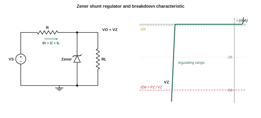
Design of the resistor is a worst-case problem with two corners. The Zener current is smallest when the supply is lowest and the load draws most current; that corner sets the largest allowed R. The Zener current is largest when the supply is highest and the load draws least; that corner sets the Zener's power rating and the smallest allowed R.
Worked problem
A 5.1 V threshold reference from the 12 V rail
The 12 V rail varies from 11.4 to 12.6 V. The comparator threshold divider and input draw between 0.5 and 2 mA. A 5.1 V, 0.5 W Zener has I_ZK = 1 mA. Choose R and check the Zener dissipation.
Show solution
- The worst case for regulation is minimum supply and maximum load.
- \[R_{max} = \frac{11.4 - 5.1}{0.001 + 0.002} = 2100\ \Omega\]
- Choose 1.8 kΩ, a standard value below the limit, to leave margin for Zener tolerance.
- The worst case for dissipation is maximum supply and minimum load.
- \[I_Z = \frac{12.6 - 5.1}{1800} - 0.0005 = 4.17 - 0.5 = 3.67\ \text{mA}\]
- \[P_Z = 5.1 \times 0.00367 \approx 18.7\ \text{mW}\]
Answer: R = 1.8 kΩ keeps the Zener above its knee at minimum supply and dissipates under 20 mW at maximum supply, far below the 0.5 W rating. The resistor itself dissipates at most (12.6 − 5.1)²/1800 ≈ 31 mW.
Line and load regulation
Using the Zener's dynamic resistance, the regulator's sensitivity to changes can be found with a simple small-signal model: the Zener becomes r_z and the circuit is a divider. Line regulation is the output change per volt of input change, and load regulation is the output change per unit of load current:
With r_z = 20 Ω and R = 1.8 kΩ, a 1 V change in the 12 V rail moves the reference only about 11 mV, and a 1 mA change in load moves it about 20 mV. That is adequate for a comparator threshold, but a shunt regulator is wasteful at higher currents, because the series resistor must carry the full load current plus the Zener current all the time, even when the load is idle. Its efficiency is roughly V_O/V_S at best.
Boosting the Zener with a transistor
To regulate larger currents, the Zener is used only as a reference, and a transistor carries the load current. In the emitter-follower regulator, the Zener holds the base of an npn transistor at V_Z, and the emitter, one base-emitter drop lower, feeds the load. The transistor's current gain means the Zener supplies only the base current, so a small Zener can control a load of an amp or more. Lesson 7 explains the transistor's role in detail. Integrated linear regulators are an elaborate version of the same idea, with a precise reference, an error amplifier and protection against overload and overheating.
# Worst-case check of a Zener shunt regulator across supply, load and tolerance
VZnom, tol, rz, IZK, PZ = 5.1, 0.05, 20.0, 1.0e-3, 0.5
R = 1800.0
worst_low, worst_high = None, None
for VS in (11.4, 12.0, 12.6):
    for IL in (0.5e-3, 2.0e-3):
        for VZ0 in (VZnom * (1 - tol), VZnom * (1 + tol)):
            # solve the divider: (VS - V)/R = IL + (V - VZ0)/rz
            V = (VS / R - IL + VZ0 / rz) / (1 / R + 1 / rz)
            IZ = (V - VZ0) / rz
            row = (IZ, VS, IL, VZ0, V)
            if worst_low is None or IZ < worst_low[0]: worst_low = row
            if worst_high is None or IZ > worst_high[0]: worst_high = row
for name, (IZ, VS, IL, VZ0, V) in (("lowest", worst_low), ("highest", worst_high)):
    print(f"{name} IZ = {IZ*1000:.2f} mA at VS = {VS} V, IL = {IL*1000:.1f} mA, VZ0 = {VZ0:.2f} V, Vout = {V:.3f} V")
print("regulates everywhere:", worst_low[0] > IZK, " power ok:", worst_high[0] * worst_high[4] < PZ / 2)lowest IZ = 1.34 mA at VS = 11.4 V, IL = 2.0 mA, VZ0 = 5.35 V, Vout = 5.382 V highest IZ = 3.77 mA at VS = 12.6 V, IL = 0.5 mA, VZ0 = 4.84 V, Vout = 4.920 V regulates everywhere: True power ok: True
Checking every corner, including part tolerance, is how Cedarline documents a design for review. The program shows that even a 5.35 V part at the top of its tolerance band, with the lowest supply and highest load, still has well over 1 mA flowing.
Transient voltage suppressors
A TVS diode is an avalanche diode built with a large junction to absorb high peak power for a short time, typically hundreds of watts to several kilowatts for a 1 ms pulse. It sits across the line to be protected and does nothing at normal voltages. When a surge drives the voltage above its breakdown, it conducts heavily and clamps the voltage, diverting the surge current to ground. Datasheets give the stand-off voltage V_WM, below which it leaks only microamps, the breakdown voltage V_BR, and the clamping voltage V_C at a stated peak pulse current. The clamping voltage is always well above V_WM, so the protected circuit must survive V_C.
Worked problem
Choosing a TVS for the 24 V input
The 24 V input can reach 28 V at the highest supply setting. A candidate TVS has V_WM = 30 V, V_BR = 33.3 V minimum and V_C = 48.4 V at a peak pulse current of 12.4 A. The board's input capacitors and regulator are rated for 50 V. Is the part suitable?
Show solution
- Normal operation: 28 V is below V_WM = 30 V, so the TVS stays off and leaks negligibly.
- During a surge the input is clamped at about 48.4 V at 12.4 A, below the 50 V rating of the parts behind it.
- The margin at full surge current is small, so a series element such as a fuse, a small resistor or an inductor in front of the TVS helps limit the current.
Answer: Yes, with little margin. Daniel adds a resettable fuse in series with the input, which also protects against a reversed or shorted supply, and specifies 63 V capacitors for extra headroom.
Clippers
A clipper, or limiter, removes the part of a waveform beyond a chosen level. A diode in series with a DC source, placed across the output after a series resistor, conducts whenever the signal exceeds the source voltage plus one diode drop and holds the output there. Two such branches facing opposite ways clip both peaks. Two back-to-back Zener diodes clip symmetrically at about ±(V_Z + 0.7) V. Clippers protect inputs, shape signals and, in audio, deliberately distort a guitar signal. The clamp circuit of lesson 2 that protected the tachometer input is a clipper whose levels are the supply rails.
Clampers and peak detectors
A clamper, or DC restorer, shifts a waveform up or down without changing its shape. A series capacitor and a diode to ground form the basic circuit. On the first negative peak the diode conducts and charges the capacitor to the peak voltage; after that the capacitor holds that charge and adds it to the input, so the output's negative peaks sit at about −0.7 V and the waveform rides above ground. Reversing the diode clamps the positive peaks instead. Video circuits use clampers to restore the black level of a signal, and the same idea, with a second diode and capacitor, gives the voltage doubler mentioned in lesson 3.
A peak detector is a diode feeding a capacitor with no load, or a light one: the capacitor charges to the highest voltage the input reaches and holds it. With a resistor across the capacitor, the held value decays slowly, and the circuit becomes an envelope detector, which recovers the audio from an AM radio signal. The accessible pedestrian signal uses exactly this idea later in the course: the microphone amplifier's output feeds a peak detector with a time constant of about a second, giving a voltage proportional to the street noise level, which the controller reads to set the locator tone's loudness.
Worked problem
Time constant for the noise-level detector
The envelope detector should follow changes in street noise over about 1 s but hold steady between the individual peaks of sound, which come at hundreds of hertz. The capacitor is 1 µF. Choose the discharge resistor.
Show solution
- Set the time constant to about 1 s.
- \[\tau = RC = 1\ \text{s} \quad \Rightarrow \quad R = \frac{1}{1 \times 10^{-6}} = 1\ \text{M}\Omega\]
- Check ripple at 200 Hz: in 5 ms the capacitor discharges by a fraction of about 5 ms / 1 s = 0.5 %, which is negligible.
Answer: A 1 MΩ resistor gives a 1 s time constant: slow enough to ignore individual cycles, fast enough to follow a passing truck.
Common mistakes
MistakeConnecting a Zener in forward bias and expecting it to regulate at V_Z.
InsteadZeners regulate in reverse breakdown; forward biased they drop about 0.7 V like any diode.
MistakeDesigning the series resistor for nominal conditions only.
InsteadCheck minimum supply with maximum load (regulation) and maximum supply with minimum load (dissipation).
MistakeAssuming a TVS clamps at its stand-off voltage.
InsteadThe clamping voltage at peak current is much higher; the protected circuit must survive V_C.
MistakeForgetting the diode drop in clipper and clamper levels.
InsteadAdd about 0.7 V (or the Zener voltage plus 0.7 V) to the reference level.
Summary and key terms
- A Zener diode regulates in reverse breakdown, modelled as V_Z0 in series with r_z.
- A shunt regulator's series resistor is chosen so I_Z stays between I_ZK and I_ZM at every corner of supply and load.
- Line and load regulation follow from a divider using r_z.
- A transistor follower lets a small Zener control a large load current.
- TVS diodes clamp surges; check stand-off, breakdown and clamping voltage at peak current.
- Clippers limit a waveform, clampers shift it, and peak and envelope detectors hold its peak value.
- Zener voltage
- The reverse breakdown voltage at which a Zener diode regulates, specified at a test current.
- Knee current
- The minimum reverse current, I_ZK, above which a Zener regulates well.
- Shunt regulator
- A regulator that holds the output by diverting excess current through an element in parallel with the load.
- Line regulation
- The change in output voltage per unit change in input voltage.
- Load regulation
- The change in output voltage per unit change in load current.
- TVS diode
- A transient voltage suppressor, an avalanche diode built to absorb surge energy.
- Clamper
- A capacitor–diode circuit that shifts the DC level of a waveform.
Practice problems
Work each problem on paper first, then reveal the answer to check.
A 9.1 V, 1 W Zener: what is its maximum current?
Show answer
1 / 9.1 ≈ 110 mA.
Design R for a 6.2 V Zener regulator from 15 to 18 V, load 0 to 10 mA, I_ZK = 1 mA.
Show answer
R_max = (15 − 6.2)/(0.011) ≈ 800 Ω; choose 750 Ω. At 18 V with no load, I_Z = 11.8/750 ≈ 15.7 mA, P_Z ≈ 97 mW.
With r_z = 10 Ω and R = 750 Ω, how much does the output change for a 1 V input change?
Show answer
About 10/760 V ≈ 13 mV.
Two back-to-back 3.3 V Zeners clip a sine wave. At about what levels?
Show answer
About ±(3.3 + 0.7) = ±4.0 V.
A clamper's diode has its anode at ground and its cathode on the output node, and the input is a ±3 V square wave. What does the output swing between?
Show answer
The diode conducts whenever the output tries to fall below −0.7 V, so the negative peaks clamp at about −0.7 V and the output swings from about −0.7 V to +5.3 V.
Why is a 5.6 V Zener a better reference over temperature than a 12 V Zener?
Show answer
Near 5 to 6 V the negative tunnelling and positive avalanche temperature coefficients nearly cancel.
Lesson quiz · 5 questions
Score 60% or more to complete this lesson.
Create a free account to save your progress, take quizzes and earn a certificate.