
ELE-240 · Lesson 2 of 12 · 27 min
Diode models and diode circuit analysis
A diode lets current flow easily in one direction and blocks it in the other. That one-way behaviour turns AC into DC, protects circuits from reversed batteries and voltage spikes, steers signals and forms the basis of every transistor. But a real diode is not a perfect switch. It needs a forward voltage of a few tenths of a volt before it conducts much, its current depends exponentially on that voltage, it leaks a little in reverse, it changes with temperature and it takes time to turn off. A designer has to decide, for each job, how much of that behaviour matters, and choose a model accordingly. This lesson builds the four models used in practice and shows how to analyze circuits with each.
At Cedarline, Amara's first task on the pedestrian controller is the 24 V DC input from the cabinet supply. The board must survive a technician connecting the supply backwards, and the tachometer input, which comes from a sensor on a long cable beside traffic, must survive spikes. Both jobs use diodes, and each needs a different level of modelling.
The diode's terminal characteristic
The diode symbol is an arrow pointing in the direction of conventional forward current, from the anode (the p side) to the cathode (the n side), with a bar marking the cathode. On a real part the cathode is marked by a band. The current–voltage curve has three regions. In forward bias, current is negligible until v_D reaches roughly 0.5 V for a small silicon diode, then rises so steeply that over a wide range of currents the voltage stays between about 0.6 and 0.8 V. In reverse bias, the current is a tiny leakage, nanoamps in a small diode at room temperature. Beyond the breakdown voltage the reverse current rises sharply.
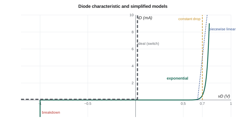
In the forward region the Shockley equation from lesson 1 reduces to i_D ≈ I_S e^{v_D/(nV_T)}, because the exponential is huge compared with 1. Taking logarithms gives a useful rule. For two currents I₁ and I₂ at voltages V₁ and V₂,
With n = 1 and V_T = 25 mV, 2.3 n V_T ≈ 60 mV: the forward voltage rises by about 60 mV for every tenfold increase in current. With n = 2 it is about 120 mV per decade. A diode carrying 1 mA at 0.70 V will therefore need about 0.76 V at 10 mA and 0.82 V at 100 mA, ignoring the extra drop across the resistance of the silicon itself, which becomes important at high current.
Temperature shifts the curve. At constant current the forward voltage falls by about 2 mV for each degree Celsius rise. This is large enough to matter: a diode at 0.70 V at 25 °C will sit near 0.58 V at 85 °C. It is also useful, since a forward-biased junction is a cheap temperature sensor, and many chips measure their own die temperature this way.
Model 1: the ideal diode
The simplest model treats the diode as a perfect switch: a short circuit when forward current flows and an open circuit when reverse voltage is applied. It is good enough whenever the circuit voltages are much larger than 0.7 V, for example when checking which way current flows in a 120 V rectifier. To analyze a circuit with ideal diodes, assume a state for each diode, solve the linear circuit, and check the assumption: an on diode must carry current in the forward direction, and an off diode must have zero or reverse voltage across it. If a check fails, change that assumption and solve again.
Model 2: constant voltage drop
The workhorse model replaces a conducting diode with a fixed voltage source V_D, usually 0.7 V for small silicon diodes, 0.3 V for Schottky diodes and about 2 V for a red LED, in the forward direction. An off diode is still an open circuit. This model gives answers within a few percent whenever the circuit voltages are a few volts or more, and it is what experienced designers use for almost all first-pass calculations.
Worked problem
Reverse-polarity protection with a series diode
The controller board draws 180 mA from the 24 V cabinet supply. Amara considers a series diode for reverse-polarity protection. Using the constant-drop model with V_D = 0.9 V for a 1 A rectifier diode at this current, find the voltage reaching the board and the power the diode dissipates.
Show solution
- With the supply connected correctly the diode is forward biased and conducts.
- \[V_{board} = 24 - 0.9 = 23.1\ \text{V}\]
- \[P_D = V_D I_D = 0.9 \times 0.18 = 0.162\ \text{W}\]
- Reversed, the diode blocks: the board sees no voltage and only leakage flows, provided the diode's reverse voltage rating exceeds 24 V with margin.
Answer: The board receives 23.1 V and the diode dissipates about 0.16 W. A Schottky diode with V_D ≈ 0.45 V would halve the loss, and a P-channel MOSFET (lesson 9) would cut it to a few millivolts.
Model 3: piecewise linear
When currents vary widely, the constant-drop model can be refined by adding a series resistance r_D: a conducting diode becomes a source V_D0 in series with r_D. The values are chosen so the straight line fits the real curve over the current range of interest. For a small diode between 1 and 10 mA, V_D0 ≈ 0.65 V and r_D ≈ 10 Ω is typical. For a power rectifier, the datasheet often gives a threshold voltage and slope resistance directly, for example 0.75 V and 25 mΩ. This model is what power-electronics designers use to estimate conduction losses, P = V_D0 I_avg + r_D I_rms².
Model 4: the exponential model and iteration
For accurate answers, especially at low currents or when only a small voltage is available, use the exponential equation itself. A diode in series with a resistor R and a source V_DD obeys two equations at once: the diode law i_D = I_S e^{v_D/(nV_T)} and Kirchhoff's voltage law i_D = (V_DD − v_D)/R. These cannot be solved in closed form, so we iterate. Guess v_D, compute i_D from the resistor, compute a new v_D from the diode law, and repeat. Two or three passes are usually enough. Newton's method converges even faster and is what circuit simulators use internally.
The same two equations can be solved graphically. The resistor equation is a straight line on the i_D–v_D plane, the load line, crossing the voltage axis at V_DD and the current axis at V_DD/R. The operating point, or quiescent point (Q-point), is where the load line meets the diode curve. The load line idea returns in lesson 6, where it shows how a transistor amplifier swings.
import math
Is, n, VT = 2.0e-14, 1.0, 0.02585     # small-signal silicon diode
VDD, R = 5.0, 1000.0

# Newton's method on f(v) = Is*(exp(v/nVT) - 1) - (VDD - v)/R
v = 0.6
for step in range(6):
    f = Is * (math.exp(v / (n * VT)) - 1) - (VDD - v) / R
    df = Is / (n * VT) * math.exp(v / (n * VT)) + 1 / R
    v -= f / df
    print(f"step {step}: vD = {v:.5f} V")
i = (VDD - v) / R
print(f"exponential model: vD = {v:.3f} V, iD = {i*1000:.3f} mA")
print(f"constant drop 0.7 V: iD = {(VDD - 0.7)/R*1000:.3f} mA")
print(f"ideal diode: iD = {VDD/R*1000:.3f} mA")step 0: vD = 1.00347 V step 1: vD = 0.97762 V step 2: vD = 0.95177 V step 3: vD = 0.92592 V step 4: vD = 0.90007 V step 5: vD = 0.87422 V exponential model: vD = 0.874 V, iD = 4.126 mA constant drop 0.7 V: iD = 4.300 mA ideal diode: iD = 5.000 mA
The comparison is the lesson. With a 5 V source, the constant-drop model is almost perfect and the ideal model is noticeably off. With a 1 V source, the constant-drop model would be badly wrong, because 0.7 V is most of the supply, and only the exponential model gives a sensible answer.
Small-signal resistance
Often a diode carries a steady DC current with a small AC signal on top, for example in a radio detector or a bias network. For signals small enough that the curve looks straight, the diode behaves like a resistor whose value is the inverse slope of the curve at the Q-point:
At 1 mA with n = 1, r_d ≈ 25 Ω; at 10 µA it is 2.5 kΩ. The resistance depends on the DC current, which means a diode can act as a current-controlled resistor, the idea behind some attenuators and automatic gain controls. Lesson 10 uses the same reasoning for transistors, where it is the foundation of all amplifier design. The rule for small-signal analysis is always the same: solve the DC circuit first to find the Q-point, then replace each nonlinear device with its small-signal model and analyze the AC circuit with DC sources set to zero.
Worked problem
Signal across a biased diode
A diode is biased at I_D = 2 mA through a large resistor, and a 10 mV peak AC signal is applied through a 1 kΩ resistor in series with a coupling capacitor. Find the AC voltage across the diode, taking n = 1 and V_T = 25 mV.
Show solution
- Find the small-signal resistance at the Q-point.
- \[r_d = \frac{nV_T}{I_D} = \frac{0.025}{0.002} = 12.5\ \Omega\]
- The signal sees a divider of 1 kΩ and r_d.
- \[v_d = 10\ \text{mV} \times \frac{12.5}{1000 + 12.5} \approx 0.123\ \text{mV}\]
Answer: About 0.12 mV peak appears across the diode. A biased diode looks like a small resistor to signals, which is why it can shunt small signals to ground.
Clamping a sensor input
The tachometer's shaft sensor delivers pulses of 0 to 12 V on a long cable, but the counter logic runs from 3.3 V and its input must stay between −0.3 V and 3.6 V. Daniel's standard input circuit uses a series resistor and two clamp diodes: one from the input node to the 3.3 V rail and one from ground to the input node. When the input tries to rise above 3.3 V plus one diode drop, the upper diode conducts and dumps the excess current into the rail; when it tries to go below ground by a diode drop, the lower diode conducts. The series resistor limits the current to a value the diodes and the rail can absorb.
Worked problem
Sizing the clamp resistor
The sensor high level is 12 V, and a cable fault could put 24 V on the line. The clamp diodes are Schottky types with V_D = 0.35 V, and the designers want to limit clamp current to 5 mA. Find the minimum series resistor.
Show solution
- At 24 V the upper diode clamps the node at 3.3 + 0.35 = 3.65 V.
- \[R \ge \frac{24 - 3.65}{0.005} = 4070\ \Omega\]
- Choose the next standard value up, 4.7 kΩ, and check its power at 24 V.
- \[P_R = \frac{(24 - 3.65)^2}{4700} \approx 0.088\ \text{W}\]
Answer: A 4.7 kΩ resistor rated 0.25 W keeps the clamp current below 5 mA even with 24 V on the line. The clamped node sits at 3.65 V, which is slightly above the 3.6 V input limit, so Daniel also checks that the 3.3 V regulator can absorb the injected current without its rail rising.
That last check is a classic trap. Clamp current flowing into a rail has to go somewhere; if the board draws less current than is being injected, the rail can be pushed up. Some designs clamp to a Zener diode or a dedicated protection device instead of the logic supply for exactly this reason.
Switching behaviour and datasheet ratings
A conducting junction diode stores minority charge, and before it can block reverse voltage that charge must be removed. When the voltage reverses, a reverse current flows briefly, the reverse recovery current, until the charge is gone. Ordinary rectifiers take several microseconds; fast-recovery types take tens to hundreds of nanoseconds. Schottky diodes, which use a metal–semiconductor junction and carry current by majority carriers only, have almost no stored charge and switch very fast, at the cost of higher leakage and lower reverse voltage ratings.
| Rating | Meaning | Design rule of thumb |
|---|---|---|
| V_RRM | Maximum repetitive peak reverse voltage | At least 1.5 to 2 times the highest reverse voltage expected |
| I_F(AV) | Maximum average forward current | Derate for temperature; check the curve at your heatsink temperature |
| I_FSM | Non-repetitive surge current | Must exceed the inrush when capacitors first charge |
| V_F | Forward voltage at a stated current | Use the maximum value, not the typical, for worst-case loss |
| I_R | Reverse leakage at a stated voltage and temperature | Check at the highest operating temperature |
| t_rr | Reverse recovery time | Matters for high-frequency rectifiers and switching circuits |
The rule in the last row of the table deserves repeating, because it applies to every component in this course. Typical values describe the middle of production; a circuit that works only with typical parts will fail in the field. Cedarline's design reviews ask for every calculation to be done with worst-case limits at the coldest and hottest operating temperatures, which for traffic equipment is commonly −40 °C to +74 °C inside the cabinet.
Common mistakes
MistakeUsing the ideal diode model when the circuit voltage is only a volt or two.
InsteadThe 0.7 V drop is a large fraction of the supply; use the constant-drop or exponential model.
MistakeForgetting to check assumed diode states.
InsteadAfter solving, confirm that on diodes carry forward current and off diodes have reverse voltage, and re-solve if not.
MistakeTreating r_d as a fixed property of the diode.
Insteadr_d = nV_T/I_D depends on the DC bias current; find the Q-point first.
MistakeDesigning with typical forward voltage and leakage.
InsteadUse datasheet maximums and check at the temperature extremes.
Summary and key terms
- A diode conducts forward above roughly 0.6 to 0.7 V (silicon) and blocks in reverse until breakdown.
- Forward voltage rises about 60 mV per decade of current (n = 1) and falls about 2 mV per °C.
- Choose the model for the job: ideal, constant drop, piecewise linear or exponential.
- Solve exponential diode circuits by iteration, Newton's method or a load line.
- For small signals a biased diode is a resistor r_d = nV_T / I_D.
- Check ratings for reverse voltage, average and surge current, recovery time and leakage at worst case.
- Anode and cathode
- The p-side and n-side terminals of a diode; forward current flows from anode to cathode.
- Constant-voltage-drop model
- A conducting diode modelled as a fixed source, about 0.7 V for silicon.
- Load line
- The straight line of the external circuit's current–voltage relation, drawn on the device curve.
- Q-point
- The DC operating point of a device, where its curve meets the load line.
- Small-signal resistance
- The inverse slope of the diode curve at the Q-point, r_d = nV_T / I_D.
- Schottky diode
- A metal–semiconductor diode with a low forward voltage and very fast switching.
- Reverse recovery
- The brief reverse current that flows while stored charge is removed when a diode turns off.
Practice problems
Work each problem on paper first, then reveal the answer to check.
A diode drops 0.68 V at 1 mA (n = 1). Estimate its voltage at 50 mA, ignoring series resistance.
Show answer
ΔV = 0.0259 ln(50) ≈ 0.101 V, so about 0.78 V.
A diode reads 0.62 V at 25 °C. Estimate its voltage at the same current at −40 °C.
Show answer
65 °C colder × 2 mV/°C ≈ +0.13 V, so about 0.75 V.
Find I through a 0.7 V diode and a 470 Ω resistor from a 3.3 V supply.
Show answer
(3.3 − 0.7)/470 ≈ 5.5 mA.
Find r_d at 0.5 mA for n = 1.
Show answer
0.0259 / 0.0005 ≈ 52 Ω.
Why is a Schottky diode preferred in a reverse-polarity protection circuit for a low-voltage board?
Show answer
Its lower forward drop wastes less voltage and power; its higher leakage is usually acceptable.
A rectifier sees a peak reverse voltage of 170 V. What V_RRM would you choose?
Show answer
At least 1.5 to 2 times, so a 400 V part, a common standard rating.
Lesson quiz · 5 questions
Score 60% or more to complete this lesson.
Create a free account to save your progress, take quizzes and earn a certificate.