
CMP-210 · Lesson 6 of 12 · 23 min
Combinational building blocks
Designing every circuit gate by gate would be slow and error-prone. Instead, designers build from a small set of standard combinational blocks that appear in almost every system: multiplexers that select one of several inputs, decoders that turn a binary code into one active line, encoders that do the reverse, and code converters such as the seven-segment decoder. Each block has a clear function that can be described in one sentence and a truth table, so it can be used without thinking about its gates. This lesson describes each block, shows how it is built, and shows how blocks are combined, including the useful trick of using a multiplexer to implement any logic function.
Thinking in blocks
A block is defined by its inputs, outputs and function, not by its internal gates. This is abstraction, the same idea that lets a programmer call a library function without reading its source code. Abstraction lets a designer reason about a large system, and it lets the blocks be reused, verified once and trusted thereafter. Hardware description languages (lesson 12) make blocks explicit as modules, and the standard blocks in this lesson are among the first modules any designer writes.
Many blocks have an enable input. When the enable is inactive, the outputs go to a fixed inactive value (or to high impedance for a tri-state block) whatever the other inputs are. Enables let blocks be combined into larger ones and let a controller turn parts of a circuit on and off. A signal that is active when low is marked with a bar or a suffix such as _n or an asterisk, and drawn with a bubble at the pin. Active-low enables and outputs are common because, historically, pulling a line low was easier and more robust than driving it high.
Multiplexers
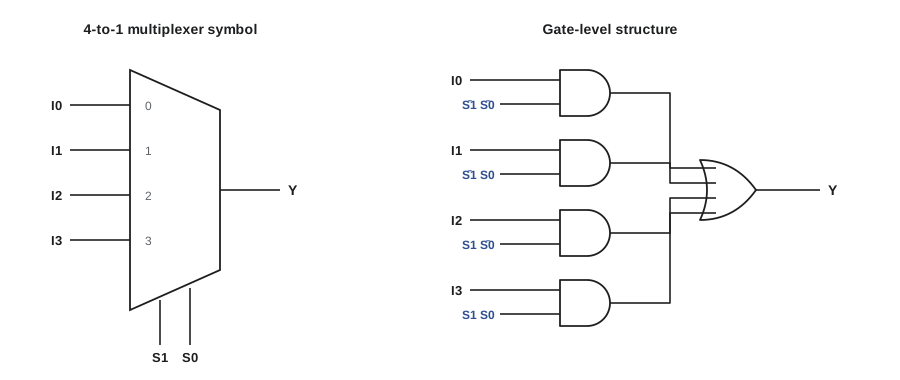
A multiplexer, or mux, is a digitally controlled selector switch. It has 2ⁿ data inputs, n select inputs and one output, and it copies to the output whichever data input the select code chooses. A 2-to-1 mux with data inputs I₀ and I₁ and select S gives Y = S̄I₀ + SI₁. A 4-to-1 mux has two select bits and four data inputs:
Each product term is a minterm of the select inputs ANDed with one data input, so a mux is an AND-OR structure with the select minterms built in. Multiplexers are everywhere: choosing which register feeds an adder in a processor, choosing which sensor an analog-to-digital converter reads, sending several slow signals over one wire in turn (time-division multiplexing), and inside programmable chips. Larger muxes are built as trees: an 8-to-1 mux can be two 4-to-1 muxes followed by a 2-to-1 mux controlled by the top select bit.
Demultiplexers and decoders
A demultiplexer does the opposite of a mux: it routes one input to one of 2ⁿ outputs chosen by the select code, and the other outputs stay inactive. A decoder is closely related. An n-to-2ⁿ decoder has n inputs and 2ⁿ outputs, and exactly one output is active, the one whose number matches the input code. Each output is simply one minterm of the inputs. A decoder with an enable input is a demultiplexer: the enable plays the role of the data input.
| A1 | A0 | Y0 | Y1 | Y2 | Y3 |
|---|---|---|---|---|---|
| 0 | 0 | 1 | 0 | 0 | 0 |
| 0 | 1 | 0 | 1 | 0 | 0 |
| 1 | 0 | 0 | 0 | 1 | 0 |
| 1 | 1 | 0 | 0 | 0 | 1 |
Decoders select things. In a memory, the address decoder activates exactly one row of storage cells. In a microcontroller system, an address decoder enables the right chip when the processor reads a particular range of addresses. In the pedestrian controller, a 3-to-8 decoder turns the 3-bit state code into separate lines, one per state, that then drive the lamps through a little OR logic.
Because a decoder produces every minterm, it can implement any function: OR together the outputs for the minterms where the function is 1. A 3-to-8 decoder and a few OR gates can produce several functions of the same three inputs at once, which is convenient when many outputs share inputs.
Worked problem
Lamp outputs from a decoded state
The pedestrian controller has six states coded in three bits: 000 main green, 001 main yellow, 010 all red, 011 side green, 100 side yellow, 101 walk. Codes 110 and 111 are unused. With a 3-to-8 decoder whose outputs are D0 to D7, write the logic for the main-street red lamp, which must be on in every state except main green and main yellow, and in the unused states for safety.
Show solution
- Main red is on in states 010, 011, 100 and 101, and in 110 and 111.
- \[R_{main} = D_2 + D_3 + D_4 + D_5 + D_6 + D_7\]
- Equivalently, main red is off only in D0 and D1, so =R_{main} = \overline{D_0 + D_1}
- In terms of the state bits S2 S1 S0, D0 + D1 = S̄2S̄1, so R_main = S2 + S1.
Answer: R_main = S2 + S1: a single 2-input OR gate, and the unused codes show red, which is the safe choice.
Encoders and priority encoders
An encoder does the reverse of a decoder: it has 2ⁿ inputs, of which one is expected to be active, and it outputs the n-bit number of the active input. An 8-to-3 encoder turns eight lines into a 3-bit code. The simple encoder fails if two inputs are active together, or if none is. A priority encoder solves this by giving each input a priority: if several inputs are active, it outputs the number of the highest-priority one, and a separate valid output says whether any input is active at all.
| I3 | I2 | I1 | I0 | Y1 | Y0 | V |
|---|---|---|---|---|---|---|
| 0 | 0 | 0 | 0 | X | X | 0 |
| 0 | 0 | 0 | 1 | 0 | 0 | 1 |
| 0 | 0 | 1 | X | 0 | 1 | 1 |
| 0 | 1 | X | X | 1 | 0 | 1 |
| 1 | X | X | X | 1 | 1 | 1 |
From the table, Y1 = I3 + I2, Y0 = I3 + Ī2I1, and V = I3 + I2 + I1 + I0. Priority encoders handle interrupt requests in processors, where several devices may ask for attention at once and the most urgent must be served first. Cedarline's controller uses one to decide which request is serviced when the pedestrian button, an emergency vehicle pre-emption input and the remote test input arrive together: emergency pre-emption always wins.
The seven-segment decoder
A BCD-to-seven-segment decoder converts a 4-bit BCD digit into the seven signals a to g that light the segments of a display. Lesson 5 minimized segment a; the full decoder has seven such functions. Displays come in two types. In a common-cathode display, all the segment LEDs share a ground connection and a segment lights when its input is high. In a common-anode display, they share the supply and a segment lights when its input is driven low, so the decoder outputs must be active-low. Each segment also needs a current-limiting resistor.
| Digit | D C B A | a | b | c | d | e | f | g |
|---|---|---|---|---|---|---|---|---|
| 0 | 0000 | 1 | 1 | 1 | 1 | 1 | 1 | 0 |
| 1 | 0001 | 0 | 1 | 1 | 0 | 0 | 0 | 0 |
| 2 | 0010 | 1 | 1 | 0 | 1 | 1 | 0 | 1 |
| 3 | 0011 | 1 | 1 | 1 | 1 | 0 | 0 | 1 |
| 4 | 0100 | 0 | 1 | 1 | 0 | 0 | 1 | 1 |
| 5 | 0101 | 1 | 0 | 1 | 1 | 0 | 1 | 1 |
| 6 | 0110 | 1 | 0 | 1 | 1 | 1 | 1 | 1 |
| 7 | 0111 | 1 | 1 | 1 | 0 | 0 | 0 | 0 |
| 8 | 1000 | 1 | 1 | 1 | 1 | 1 | 1 | 1 |
| 9 | 1001 | 1 | 1 | 1 | 1 | 0 | 1 | 1 |
With four digits on the tachometer, Amara does not need four decoders. She uses one decoder and multiplexes the display: the digits are lit one at a time, each for a couple of milliseconds, with a 4-to-1 mux choosing which BCD digit feeds the decoder and a 2-to-4 decoder enabling the matching digit's common terminal. If the whole cycle repeats faster than about 60 times a second, the eye sees all four digits steadily lit. This saves pins and parts and is used in almost every multi-digit LED display.
Logic functions from multiplexers
A 2ⁿ-to-1 multiplexer can implement any function of n variables: connect the variables to the select inputs and wire each data input to the function's value (0 or 1) for that row of the truth table. The mux becomes a lookup table, which is exactly how the logic cells of field-programmable gate arrays work (lesson 12). Better still, a 2ⁿ-to-1 mux can implement any function of n + 1 variables. Put n variables on the selects, and for each row group, connect the data input to 0, 1, the remaining variable or its complement. This is Shannon's expansion from lesson 3 in hardware.
Worked problem
The walk-request function on a 4-to-1 mux
Implement W(P, M, T) = Σm(1, 3, 4, 5, 7) with a 4-to-1 multiplexer, using P and M as the select inputs.
Show solution
- For each combination of P and M, look at the two rows (T = 0 and T = 1) and express W in terms of T.
- P M = 00: rows 0 and 1 give W = 0, 1, so I₀ = T.
- P M = 01: rows 2 and 3 give W = 0, 1, so I₁ = T.
- P M = 10: rows 4 and 5 give W = 1, 1, so I₂ = 1.
- P M = 11: rows 6 and 7 give W = 0, 1, so I₃ = T.
Answer: Select inputs P, M; data inputs I₀ = T, I₁ = T, I₂ = 1, I₃ = T. No other gates are needed.
# A multiplexer as a lookup table, and Shannon expansion onto a smaller mux
from itertools import product

def mux(selects, data):
    index = 0
    for s in selects:
        index = index * 2 + s
    return data[index]

def W(P, M, T):
    return int((P and not M) or T)

# 8-to-1 mux: the data inputs are just the truth table
table = [W(*row) for row in product((0, 1), repeat=3)]
# 4-to-1 mux with P, M on the selects: data inputs are 0, 1, T or not T
residues = []
for P, M in product((0, 1), repeat=2):
    pair = (W(P, M, 0), W(P, M, 1))
    residues.append({(0, 0): "0", (1, 1): "1", (0, 1): "T", (1, 0): "T'"}[pair])
print("8-to-1 data inputs:", table)
print("4-to-1 data inputs:", residues)
ok = all(mux((P, M, T), table) == W(P, M, T) for P, M, T in product((0, 1), repeat=3))
print("8-to-1 mux matches W on all rows:", ok)8-to-1 data inputs: [0, 1, 0, 1, 1, 1, 0, 1] 4-to-1 data inputs: ['T', 'T', '1', 'T'] 8-to-1 mux matches W on all rows: True
Buses and tri-state buffers
When many sources must share a set of wires, two arrangements are possible. A multiplexer chooses one source and drives the shared wires through its output. Alternatively, each source drives the wires through tri-state buffers, and a decoder enables exactly one source at a time while all the others are in high impedance. Inside chips, multiplexers are preferred because they are easier to test and cannot cause contention. On boards and in older systems, tri-state buses such as a microprocessor's data bus remain common, and the designer must guarantee that two drivers are never enabled together.
Hierarchical design with blocks
Larger blocks are made from smaller ones. A 4-to-16 decoder can be built from two 3-to-8 decoders whose enables are driven by the top address bit and its complement, or from five 2-to-4 decoders arranged as a tree. A 16-to-1 multiplexer can be built from five 4-to-1 muxes. Building hierarchically is not always the fastest arrangement, but it lets each piece be designed and tested once. Daniel's design reviews at Cedarline always start from the block diagram before anyone looks at gates.
Common mistakes
MistakeTreating an encoder as safe when several inputs may be active.
InsteadUse a priority encoder, and check its valid output for the no-input case.
MistakeDriving a common-anode display with active-high segment signals.
InsteadCommon-anode segments light when driven low; use active-low decoder outputs.
MistakeAssuming a 2ⁿ-to-1 mux handles only n-variable functions.
InsteadWith 0, 1, a variable or its complement on the data inputs, it handles n + 1 variables.
MistakeLeaving decoded unused states with no defined output.
InsteadDecide what each unused code does; in a controller, make it safe.
MistakeEnabling two tri-state drivers on one bus.
InsteadDrive the enables from a decoder so that exactly one is active.
Summary and key terms
- Standard blocks are defined by function, which lets designers work at a higher level of abstraction.
- A 2ⁿ-to-1 multiplexer selects one data input with n select bits; it is an AND-OR of select minterms.
- An n-to-2ⁿ decoder activates the one output matching its input code; with an enable it is a demultiplexer.
- A priority encoder outputs the number of the highest-priority active input plus a valid flag.
- A BCD-to-seven-segment decoder converts digits for displays; multiplexing lets one decoder drive several digits.
- A multiplexer can implement any function as a lookup table, using Shannon expansion to save one select input.
- Multiplexer
- A block that copies one of 2ⁿ data inputs to its output under control of n select inputs.
- Decoder
- A block with n inputs and 2ⁿ outputs, exactly one of which is active.
- Demultiplexer
- A block that routes one input to one of several outputs chosen by a select code.
- Priority encoder
- An encoder that outputs the number of the highest-priority active input.
- Enable
- An input that activates a block; when inactive, the outputs take a fixed or high-impedance value.
- Active-low
- A signal that performs its function when it is at logic 0.
Practice problems
Work each problem on paper first, then reveal the answer to check.
Write the output expression of an 8-to-1 mux with selects S2 S1 S0.
Show answer
Y = Σ (minterm i of S2 S1 S0) · Iᵢ for i = 0 to 7.
How many 2-to-4 decoders are needed to build a 4-to-16 decoder as a tree?
Show answer
Five: one decodes the top two bits to enable one of four second-level decoders.
For the 4-input priority encoder, what is the output when I2 and I0 are both 1?
Show answer
Y = 10 (input 2) and V = 1.
Implement F(A,B,C) = Σm(0, 3, 5, 6) with a 4-to-1 mux using A and B as selects.
Show answer
AB = 00: C̄; 01: C; 10: C; 11: C̄. F is 1 when an even number of inputs are 1, the complement of A ⊕ B ⊕ C.
Which segments are lit for the digit 7?
Show answer
a, b and c.
A four-digit display is refreshed every 4 ms per digit. What is the overall refresh rate?
Show answer
One cycle takes 16 ms, about 62.5 Hz, just fast enough to avoid flicker.
Lesson quiz · 5 questions
Score 60% or more to complete this lesson.
Create a free account to save your progress, take quizzes and earn a certificate.