
CIV-421 · Lesson 9 of 12 · 18 min
Masonry walls under axial load and slenderness
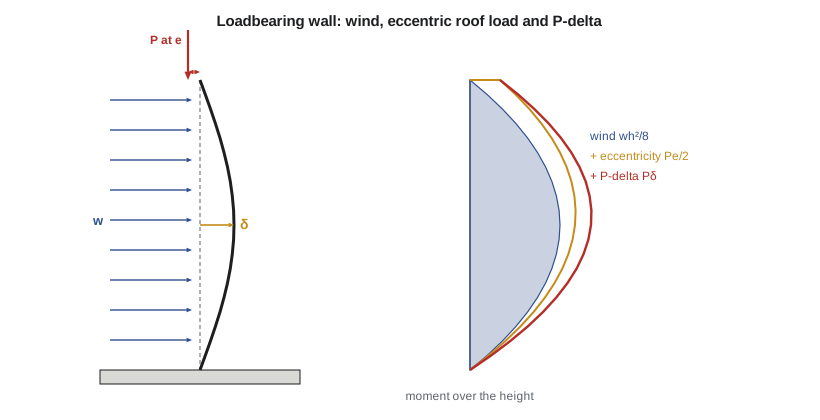
Loadbearing masonry walls carry the roof and floors as well as wind. The axial load helps in one way, because compression closes cracks and adds to the flexural resistance of a reinforced wall, and hurts in another, because a slender wall that deflects under wind carries its axial load at an eccentricity that grows with the deflection. This second-order, or P-delta, effect is what limits tall, thin masonry walls. This lesson completes the design of the pump house walls under the combined effects of roof load, eccentricity, wind and slenderness.
Axial load on the pump house walls
The roof joists span 7.2 m and bear on the two long walls through steel bearing plates set on the bond beam. Each long wall receives a specified roof dead load of 3.6 kN/m and snow load of 9.36 kN/m. The bearing is near the inside face, so the reaction acts at an eccentricity of about 60 mm from the centre of the wall. The wall's own weight, 2.6 kPa over its 5.0 m height, adds 13 kN/m at the base and 6.5 kN/m at mid-height, where the moment from wind is largest.
Axial capacity on its own
Before adding bending, it helps to see how much axial load the wall could carry. For a wall loaded concentrically, the factored axial resistance is based on \(0.85\phi_m f'_m A_e\), where \(A_e\) is the effective area of the face shells and grouted cores, reduced for slenderness. For the pump house wall, \(0.85(0.60)(10)(92\,000) = 469\) kN per metre before the slenderness reduction. The bars are not counted in compression because they are not enclosed by ties. Against the largest factored axial load, 27 kN/m under full snow, the wall is barely loaded. Low-rise masonry walls are almost never limited by axial load alone; bending, and the way axial load interacts with it, decides the design.
The same reasoning explains why so many masonry buildings of three to six storeys are loadbearing: the walls have large reserves in compression, and floors bearing on them add stability against wind. What limits taller loadbearing masonry is usually earthquake load and the ductility of the walls, which lesson 10 introduces.
The first-order moment
For a wall pinned at top and bottom with a reaction \(P_t\) at eccentricity \(e\) at the top and a uniform lateral load \(w\), the first-order moment at mid-height is
The eccentricity term is half the end moment because the moment from an end couple varies linearly from \(P_te\) at the top to zero at the bottom. Under gravity load alone, the eccentric reaction bends the wall toward the inside; with wind blowing inward or outward, the two effects add or subtract, and both directions are checked.
Second-order effects
As the wall deflects by \(\delta\) at mid-height, the axial load \(P\) at that level acts on a lever arm \(\delta\), adding \(P\delta\) to the moment. The extra moment increases the deflection, which increases the moment again. The process converges if the wall is stiff enough; if not, the wall buckles. A cracked reinforced masonry wall is much less stiff than the uncracked section, so the deflection, and with it the P-delta moment, can grow quickly once the wall cracks.
S304 allows two approaches. The moment magnifier method multiplies the first-order moment by a factor \(C_m/(1 - P_f/P_{cr})\), with the critical load computed from an effective stiffness that the standard gives as a function of the eccentricity, between the cracked stiffness and a fraction of the uncracked stiffness, and with a reduction for sustained load. The alternative is a second-order analysis that computes the deflection directly with cracked and uncracked stiffness and iterates. The team uses the second approach in Sofia's script, with the cracked stiffness beyond the cracking moment, which is consistent with the standard's lower bound and easy to check.
The cracked moment of inertia per metre comes from the transformed section, with the compression zone in the face shell and the steel transformed by \(n = E_s/E_m\). The flexural resistance with axial load is computed by adding the axial force to the steel force in the equilibrium of the section, because compression from the roof reduces the net tension the steel must carry.
# Lesson 9: pump house wall under roof load, wind and P-delta (S304 format, second-order iteration)
import math
t, fs_t, h = 190.0, 32.0, 5000.0
fm, fy, Es = 10.0, 400.0, 200000.0
phim, phis = 0.60, 0.85
Em = 850 * fm
As, d, b = 250.0, 95.0, 1000.0          # 15M @ 800 mm, per metre
e = 60.0                                 # mm, eccentricity of the roof reaction
D, S, W = 3.6, 9.36, 0.80                # roof dead and snow (kN/m), specified wind (kPa)
wall = 2.6 * h / 1e3                     # kN/m, wall self-weight over the full height
In = 2 * (b * fs_t**3 / 12 + b * fs_t * (t / 2 - fs_t / 2)**2)   # face shells (uncracked)
n = Es / Em
c = (-n * As + math.sqrt((n * As)**2 + 2 * b * n * As * d)) / b   # cracked neutral axis (in face shell)
Icr = b * c**3 / 3 + n * As * (d - c)**2
Mcr = 0.65 * In / (t / 2) / 1e6
print(f"Em = {Em:.0f} MPa, n = {n:.1f}, c = {c:.1f} mm, In = {In/1e6:.0f} x 10^6, Icr = {Icr/1e6:.1f} x 10^6 mm4/m")

def check_case(name, gD, gS, gW):
    Pt = gD * D + gS * S                 # factored load at the top
    Pm = Pt + gD * wall / 2              # at mid-height
    w = gW * W
    M0 = w * (h / 1e3)**2 / 8 + Pt * e / 1e3 / 2
    delta, M = 0.0, M0
    for _ in range(30):
        M = M0 + Pm * delta / 1e3
        if M <= Mcr:
            dnew = 5 * M * 1e6 * h**2 / (48 * Em * In)
        else:
            dnew = 5 * Mcr * 1e6 * h**2 / (48 * Em * In) + 5 * (M - Mcr) * 1e6 * h**2 / (48 * Em * Icr)
        if abs(dnew - delta) < 0.01:
            break
        delta = dnew
    T = phis * As * fy / 1e3                         # kN/m
    a = (T + Pm) * 1e3 / (0.85 * phim * fm * b)
    Mr = (T + Pm) * (d - a / 2) / 1e3                # axial load adds to the compression resultant
    print(f"{name}: P = {Pm:.1f} kN/m, M first-order = {M0:.2f}, delta = {delta:.1f} mm, "
          f"M = {M:.2f} kN.m/m, Mr = {Mr:.2f}, ratio {M/Mr:.2f}")

check_case("1.25D + 1.5S + 0.4W", 1.25, 1.5, 0.4)
check_case("1.25D + 1.4W + 0.5S", 1.25, 0.5, 1.4)
check_case("0.9D + 1.4W        ", 0.9, 0.0, 1.4)
print(f"Slenderness h/t = {h/t:.1f}")
check_case("service: D + W      ", 1.0, 0.0, 1.0)
print(f"Service deflection limit often used: 0.007h = {0.007*h:.0f} mm")Em = 8500 MPa, n = 23.5, c = 28.1 mm, In = 405 x 10^6, Icr = 33.7 x 10^6 mm4/m 1.25D + 1.5S + 0.4W: P = 26.7 kN/m, M first-order = 1.56, delta = 1.2 mm, M = 1.59 kN.m/m, Mr = 9.39, ratio 0.17 1.25D + 1.4W + 0.5S: P = 17.3 kN/m, M first-order = 3.78, delta = 13.3 mm, M = 4.01 kN.m/m, Mr = 8.69, ratio 0.46 0.9D + 1.4W : P = 9.1 kN/m, M first-order = 3.60, delta = 10.5 mm, M = 3.69 kN.m/m, Mr = 8.07, ratio 0.46 Slenderness h/t = 26.3 service: D + W : P = 10.1 kN/m, M first-order = 2.61, delta = 2.0 mm, M = 2.63 kN.m/m, Mr = 8.15, ratio 0.32 Service deflection limit often used: 0.007h = 35 mm
Worked problem
Combined loading on the pump house wall
Check the 190 mm wall with 15M at 800 mm (\(f'_m = 10\) MPa, \(E_m = 8500\) MPa) under \(1.25D + 1.4W + 0.5S\), with the roof reaction at \(e = 60\) mm.
Show solution
- Loads at the top and at mid-height:
- \[P_t = 1.25(3.6) + 0.5(9.36) = 9.2\ \text{kN/m} \qquad P = 9.2 + 1.25(6.5) = 17.3\ \text{kN/m}\]
- \[M_0 = \frac{1.4(0.80)(5.0)^2}{8} + \frac{9.2(0.060)}{2} = 3.50 + 0.28 = 3.78\ \text{kN·m/m}\]
- Section properties: \(I_n = 405 \times 10^6\) mm⁴/m (face shells), \(n = 23.5\), \(c = 28.1\) mm, \(I_{cr} = 33.7 \times 10^6\) mm⁴/m, \(M_{cr} \approx 2.77\) kN·m/m.
- Iterating, the deflection converges at \(\delta = 13.3\) mm:
- \[M = 3.78 + 17.3(0.0133) = 4.01\ \text{kN·m/m}\]
- \[a = \frac{(0.85 \times 250 \times 400 + 17\,300)}{0.85(0.60)(10)(1000)} = 20.1\ \text{mm} \qquad M_r = (85\,000 + 17\,300)\Big(95 - \frac{20.1}{2}\Big) = 8.69\ \text{kN·m/m}\]
Answer: The ratio is 0.46. The P-delta moment adds about 6 per cent to the first-order moment, which is modest because the wall is not very slender (\(h/t = 26\)) and the axial load is light. The case with 0.9D and full wind gives almost the same ratio, because the smaller axial load reduces both the P-delta moment and the resistance; the gravity case with full snow is far from critical.
Two results deserve a second look. First, the 0.9D case can govern even though the loads are smaller, because the axial compression that helps the section is reduced; designers always check minimum gravity with maximum wind. Second, the service deflection under wind is only about 2 mm (0.1 in.), far below common limits such as 0.007 times the height, because the wall stays uncracked at service load. The deflection only becomes large after cracking, at factored load.
Slenderness limits and very tall walls
The pump house walls have \(kh/t = 26\). S304 permits walls with higher slenderness, but above certain limits it requires the slenderness to be considered explicitly and, for very slender walls, imposes extra conditions on the axial load and the reinforcement. Tall walls in warehouses and gymnasiums, 8 to 10 m (25 to 35 ft) high, are often thickened to 240 or 290 mm block, or stiffened by pilasters, to keep the P-delta effect under control.
Concentrated loads and bearing
The joists deliver their reactions at discrete points, not as a smooth line load. Directly under a bearing plate, the masonry carries a concentrated compression that spreads downward at roughly 2 vertical to 1 horizontal through the bond beam and the courses below. The bearing stress under the plate is checked against the bearing resistance of the masonry, and the bond beam under the bearing spreads the load along the wall. For heavy concentrated loads, such as a girder bearing, the cores under the bearing are grouted solid for several courses, or a concrete pier is built into the wall.
Columns and pilasters
Masonry columns and pilasters are compression members with ties around the vertical bars, designed much like reinforced concrete columns with the masonry stress block and resistance factors. They are limited in slenderness and must have a minimum number and size of bars and ties. At the wash bay, the door jambs are reinforced as pilasters, with two bars in grouted cores at each jamb, because they collect the load from the lintel over the 4.2 m (14 ft) overhead door and the wind on half the door.
Lintels over openings
Over each door and window, a lintel carries the masonry and roof load above the opening. Lintels in block walls are usually reinforced bond beams, one or two courses deep, designed as reinforced masonry beams in flexure and shear. Arching action in the masonry above means that the lintel often carries only a triangle of wall, not the full height, provided there is enough wall beside the opening to resist the thrust. The overhead door in the wash bay needs a deep lintel, three courses with two 15M (#5) bars in the bottom course, because the roof joists bear on it.
Common mistakes
MistakeChecking only the case with maximum gravity load.
InsteadMinimum gravity with maximum wind (0.9D) often governs reinforced walls, because the axial load that helps the section is smaller.
MistakeUsing the uncracked moment of inertia after the wall cracks.
InsteadBeyond the cracking moment, use the cracked moment of inertia; the deflection and P-delta moment grow quickly.
MistakeApplying the roof reaction at the centre of the wall.
InsteadJoists bearing near one face apply an eccentricity; include the \(P_te/2\) term.
MistakeIgnoring concentrated loads under bearing plates.
InsteadCheck bearing and grout the cores under heavy reactions.
Summary and key terms
- First-order moment at mid-height: \(M_0 = wh^2/8 + P_te/2\).
- Second-order (P-delta) moment: \(P\delta\), with \(\delta\) from uncracked stiffness up to \(M_{cr}\) and cracked stiffness beyond.
- Axial compression adds to the flexural resistance of a reinforced wall but also drives the P-delta moment.
- The pump house wall: 4.01 kN·m/m against 8.69 under \(1.25D + 1.4W + 0.5S\) (0.46); service deflection about 2 mm.
- Lintels, pilasters and grouted bearings handle openings and concentrated loads.
- P-delta effect
- The additional moment from axial load acting on the deflected shape of a member.
- Eccentricity
- The distance from the centre of the wall to the line of action of an applied load.
- Cracked moment of inertia
- The moment of inertia of the transformed section after the masonry cracks in tension.
- Moment magnifier
- A factor that increases first-order moments to allow for second-order effects.
- Slenderness ratio
- The effective height of a wall divided by its thickness.
- Pilaster
- A thickened or reinforced column within a masonry wall.
- Lintel
- A beam over an opening in a wall.
- Arching action
- The tendency of masonry above an opening to span as an arch and relieve the lintel.
Practice problems
Work each problem on paper first, then reveal the answer to check.
Why does the P-delta moment grow quickly after a reinforced wall cracks?
Show answer
The cracked stiffness is a small fraction of the uncracked stiffness, so the deflection, and the P-delta moment with it, rise sharply.
If the eccentricity of the roof reaction were 95 mm, at the face of the wall, how would \(M_0\) change in the governing case?
Show answer
\(P_te/2\) rises from 0.28 to 0.44 kN·m/m, so \(M_0\) becomes 3.94 kN·m/m.
Why is the service deflection so small compared with the factored deflection?
Show answer
At service load the wall is uncracked, so it is many times stiffer.
How can a designer control slenderness in a tall masonry wall?
Show answer
Use thicker units, add pilasters or intermediate supports, or reduce the height between lateral supports.
Lesson quiz · 5 questions
Score 60% or more to complete this lesson.
Create a free account to save your progress, take quizzes and earn a certificate.