
CIV-421 · Lesson 5 of 12 · 21 min
Wood connections
Connections are where timber structures succeed or fail. A wood member is easy to size, but its strength means little unless the load can be passed into it and out again through nails, screws, bolts, dowels, timber rivets, split rings or proprietary hardware. Wood is weak across the grain and in shear, so a careless connection can split a member long before the member itself is stressed. This lesson explains how dowel-type fasteners carry load, applies the yield model to the knife-plate connection at the pavilion beam ends, and covers the spacing, edge distance and splitting rules that keep connections ductile.
Types of fasteners
Nails are the most common fasteners in light-frame construction, used by the thousands in every shear wall, floor and roof. Wood screws and modern self-tapping screws, now available up to 600 mm (24 in.) long, can be driven without pre-drilling and carry both lateral load and withdrawal; long screws installed at an angle make stiff, strong connections in mass timber. Bolts and drift pins (dowels) carry large loads through steel side plates or knife plates. Timber rivets, split rings and shear plates are older, high-capacity connectors. Proprietary hangers and concealed connectors, tested by their manufacturers, are now the usual way to connect mass timber beams to columns.
Fasteners load wood in two ways: laterally, with the fastener bending and bearing on the wood around it, and in withdrawal, with the fastener being pulled out along its axis. Smooth nails are poor in withdrawal and should not be used to resist sustained pull-out; threaded screws and ring-shank nails are much better.
The yield model
When a dowel-type fastener is loaded laterally, the wood under it crushes and the fastener bends. The European yield model, developed by Johansen in 1949 and the basis of both the Canadian and the American standards, predicts the capacity by assuming that both the wood and the fastener behave as rigid-plastic materials. The wood has an embedment (dowel bearing) strength, and the fastener forms plastic hinges at its yield moment. Each possible combination of crushing and hinging is a yield mode, and the lowest one governs.
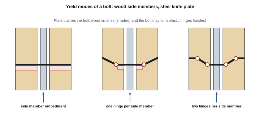
For a connection with a steel main plate, the knife plate, and two wood side members, three modes matter. In the first, the bolt stays straight and crushes the wood along the full thickness of each side member. In the second, the bolt forms one plastic hinge in each side member, and the wood crushes only near the plate. In the third, two hinges form in each side member, and very little wood crushes. Thick wood and slender bolts favour the hinge modes, which are ductile; thin wood and stiff bolts favour pure embedment.
The embedment strength depends on the relative density \(G\) of the wood, the fastener diameter and the angle between the load and the grain. For bolts and dowels, O86 gives expressions of the form \(f_1 = 50G(1 - 0.01d)\) MPa parallel to grain and about \(22G(1 - 0.01d)\) perpendicular to grain, where \(d\) is the diameter in millimetres. The perpendicular value is less than half the parallel value, which matters at the pavilion beam ends, where the beam reaction acts across the grain.
O86 then gives the factored lateral resistance of a bolted connection as \(N_r = \phi\,n_u\,n_s\,n_F\,J\), where \(n_u\) is the lowest yield-mode value per shear plane, \(n_s\) the number of shear planes, \(n_F\) the number of fasteners, \(J\) a set of factors for row effects and other conditions, and \(\phi = 0.8\). The yield equations are written so that each mode depends on the embedment strengths, the bolt yield strength (310 MPa for common bolts), the diameter and the member thicknesses.
The pavilion beam-to-column connection
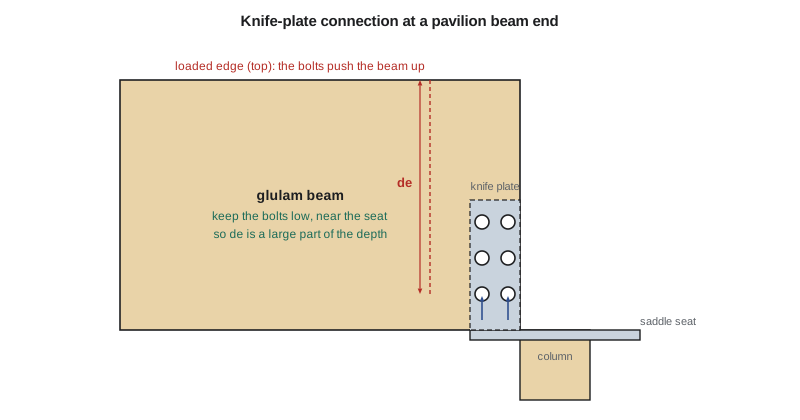
At each column, the two beam ends sit on a steel saddle, and a 9.5 mm knife plate welded to the saddle projects up into a slot cut in the end of each beam. Bolts of 19 mm (3/4 in.) diameter pass through the beam and the plate. The bolts carry the beam reaction of 75.4 kN down into the plate, so the load on each bolt acts perpendicular to the grain of the beam. Each wood side member is \((175 - 9.5 - 3)/2 = 81.2\) mm thick, allowing 3 mm for slot tolerance.
# Lesson 5: bolted knife-plate connection at the pavilion beam ends (yield model, CSA O86 format)
import math
d = 19.05                       # bolt diameter (mm), 3/4 in. bolts
fy = 310.0                      # bolt yield strength used in the yield equations (MPa)
G = 0.49                        # mean relative density, Douglas fir-larch glulam
f1 = 50 * G * (1 - 0.01 * d)    # embedment parallel to grain (MPa)
f2 = 22 * G * (1 - 0.01 * d)    # embedment perpendicular to grain (MPa)
fs = 1.5 * 400.0                # bearing strength of the 9.5 mm steel knife plate (MPa)
tp, b_beam = 9.5, 175.0
t1 = (b_beam - tp - 3.0) / 2    # each wood side member, allowing a 3 mm slot tolerance

def per_plane(fw, ts):
    """Lowest yield mode for one shear plane, wood side member on a steel main plate."""
    Re = fs / fw
    m_side = fw * d * ts                                   # side member embedment
    k3 = -1 + math.sqrt(2 * (1 + Re) / Re + 2 * fy * (2 + Re) * d**2 / (3 * fs * ts**2))
    m_III = k3 * d * ts * fs / (2 + Re)                    # one hinge in the bolt
    m_IV = d**2 * math.sqrt(2 * fs * fy / (3 * (1 + Re)))  # two hinges in the bolt
    m_main = fs * d * tp / 2                               # steel plate bearing, per plane
    modes = {"side embedment": m_side, "one hinge": m_III, "two hinges": m_IV, "plate bearing": m_main}
    return min(modes.items(), key=lambda kv: kv[1]), modes

Vf = 75.4
print(f"t1 = {t1:.1f} mm, f1 = {f1:.1f} MPa, f2 = {f2:.1f} MPa")
for label, fw in [("load parallel to grain (column)", f1), ("load perpendicular to grain (beam)", f2)]:
    (mode, val), modes = per_plane(fw, t1)
    nu = 2 * val / 1e3                                     # two shear planes, kN per bolt
    print(f"{label}: governing mode = {mode}, nu = {nu:.1f} kN per bolt")
    for k, v in modes.items():
        print(f"     {k:15s} {v/1e3:6.1f} kN per plane")
    nr = 0.8 * nu                                          # phi = 0.8
    n = math.ceil(Vf / nr)
    print(f"     phi nu = {nr:.1f} kN, bolts needed for Vf = {Vf} kN: {n}")

# Uplift on the CLT roof: self-tapping screws from panel to beam
wnet = 1.4 * 1.1 - 0.9 * 1.2      # kPa: factored wind suction 1.1 kPa less 0.9 x dead
trib = 3.0 * 0.6                  # m2 per screw at 600 mm along each beam
print(f"\nUplift: net factored suction {wnet:.2f} kPa, force per screw at 600 mm = {wnet*trib:.2f} kN")t1 = 81.2 mm, f1 = 19.8 MPa, f2 = 8.7 MPa
load parallel to grain (column): governing mode = one hinge, nu = 36.6 kN per bolt
side embedment 30.7 kN per plane
one hinge 18.3 kN per plane
two hinges 22.9 kN per plane
plate bearing 54.3 kN per plane
phi nu = 29.3 kN, bolts needed for Vf = 75.4 kN: 3
load perpendicular to grain (beam): governing mode = one hinge, nu = 21.9 kN per bolt
side embedment 13.5 kN per plane
one hinge 11.0 kN per plane
two hinges 15.3 kN per plane
plate bearing 54.3 kN per plane
phi nu = 17.5 kN, bolts needed for Vf = 75.4 kN: 5
Uplift: net factored suction 0.46 kPa, force per screw at 600 mm = 0.83 kNWorked problem
Bolts for the beam end
Find the number of 19 mm bolts needed for \(V_f = 75.4\) kN, with the load perpendicular to grain in 24f-EX Douglas fir-larch glulam (\(G = 0.49\)).
Show solution
- Embedment strength perpendicular to grain:
- \[f_2 = 22(0.49)(1 - 0.19) = 8.7\ \text{MPa}\]
- Yield modes per shear plane: side embedment 13.5 kN, one hinge 11.0 kN, two hinges 15.3 kN, plate bearing 54.3 kN. The one-hinge mode governs:
- \[n_u = 2(11.0) = 21.9\ \text{kN per bolt (two shear planes)} \qquad \phi n_u = 0.8(21.9) = 17.5\ \text{kN}\]
- \[n_F = \frac{75.4}{17.5} = 4.3 \to 5\ \text{bolts; use 6 in two rows of 3}\]
Answer: Six bolts give \(6(17.5) = 105\) kN against 75.4 kN. Loaded parallel to grain, the same bolt would carry 29.3 kN, so only three would be needed: the direction of load relative to grain changes the design completely. The one-hinge mode, which governs here, is ductile, which is what the designer wants.
Splitting perpendicular to grain
A force applied across the grain through fasteners must be carried from the fasteners into the rest of the member. The wood on the side of the fasteners away from the direction of the force, toward the unloaded edge, has to hang from them in tension perpendicular to grain. Wood is very weak in that direction, so the member can split along the fastener line, suddenly and without warning. The protection is to place the fasteners far from the loaded edge, the edge toward which the fastener forces push, so that most of the depth lies between them and that edge, and to check splitting explicitly. For a load hung from a beam, the loaded edge is the bottom and the bolts go high. At a beam support, the bolts push the beam upward, the loaded edge is the top, and the bolts go low, near the seat.
O86 checks splitting with a resistance that grows with the loaded-edge distance \(d_e\), the distance from the loaded edge to the fastener farthest from it, and with the member thickness. The design lever is the same as in the American approach: placing the bolt group in the lower part of the beam end, so that \(d_e\) is a large fraction of the depth, multiplies the splitting resistance. In the pavilion connection, the two rows of bolts sit in the bottom 200 mm of the 532 mm beam, just above the seat, giving \(d_e\) of about 430 mm, and Owen confirms the splitting check with the standard's expression.
An alternative that many designers prefer is to let the beam bear directly on the saddle, so the vertical reaction passes in bearing and the bolts only keep the beam in place. The pavilion detail does both: the beam bears on the saddle seat, and the bolts, sized for the full reaction as a second load path, hold the beam against uplift and lateral load. The design is robust if either path is imperfect.
Spacing, end and edge distances
Fasteners too close to each other or to the ends and edges of a member split the wood before the yield modes develop. Both standards give minimum spacings along and across the grain, end distances and edge distances, all in multiples of the diameter, with larger values for loaded ends in tension. For bolts loaded parallel to grain, typical values are four diameters between bolts in a row, a seven-diameter end distance in tension and one and a half diameters to an unloaded edge. For loads perpendicular to grain, the loaded edge needs four diameters or more.
Rows of bolts parallel to the grain also share load unevenly: the bolts at the ends of a long row take more than their share, and a row of ten bolts does not carry ten times the load of one. The standards reduce the capacity of long rows through row and group action factors, and brittle failure modes, such as row tear-out and group tear-out, where a block of wood shears out along the rows, must be checked for groups with many fasteners. Using fewer, larger groups of shorter rows, or self-tapping screws that reinforce the wood, avoids the problem.
Nails and screws
Nailed connections use the same yield model with embedment strengths for nails, and the many small nails in a shear wall act together as a ductile system. A 3.25 mm common nail in S-P-F has a unit lateral resistance in the order of 1 kN, depending on the side member, so a shear wall with nails at 150 mm resists several kilonewtons per metre; lesson 6 uses this. Withdrawal resistance of smooth nails is low and drops further if the wood dries after driving, so nails are not used to resist sustained withdrawal.
Self-tapping screws have changed mass timber design. Installed at 45 degrees across a joint, they load the wood along the screw axis, in withdrawal, where wood is stiff and strong, rather than in lateral bearing. They also reinforce wood against splitting near notches and at beam supports. Their design values come from evaluation reports for each product. At the pavilion, screws fix the CLT deck to the glulam beams, resisting the uplift from wind suction on the roof: Sofia's script shows a small net uplift per screw, which a single screw at 600 mm (24 in.) carries easily, though the spacing is set closer to make the deck act as a diaphragm.
Moisture and connections
Connections are sensitive to moisture changes. A steel plate bolted across the width of a deep glulam beam restrains the wood from shrinking as it dries; if the bolts are far apart across the grain, the shrinking wood splits between them. Good details use bolts in a single column or short groups across the grain, slotted holes in the steel, or several separate plates, so the wood can move. Wet service reduces fastener capacity and corrodes ordinary steel, which is why the salt shed uses hot-dip galvanized or stainless fasteners throughout.
Common mistakes
MistakeUsing the parallel-to-grain embedment strength for a beam reaction carried by bolts.
InsteadA beam reaction loads the bolts across the grain; use the perpendicular strength, less than half the parallel value.
MistakePlacing the bolts of a beam support connection high in the beam.
InsteadThe support force pushes up, so the top is the loaded edge; keep the bolts low, near the seat, and check splitting.
MistakeCounting a long row of bolts at full capacity per bolt.
InsteadApply row and group factors and check row and group tear-out.
MistakeBolting a steel plate across the full depth of a deep beam with widely spaced bolts.
InsteadAllow for shrinkage across the grain with slotted holes, short groups or separate plates.
Summary and key terms
- Dowel-type fasteners carry lateral load by wood embedment and fastener bending; the yield model checks each mode and the lowest governs.
- Embedment for bolts: about \(50G(1 - 0.01d)\) MPa parallel and \(22G(1 - 0.01d)\) perpendicular to grain; \(N_r = \phi n_u n_s n_F J\) with \(\phi = 0.8\).
- Loads across the grain risk splitting; keep fasteners far from the loaded edge (low at a beam support, high under a hung load) and check the loaded-edge distance.
- Spacing, end and edge distances, row factors and tear-out checks keep connections ductile.
- The pavilion beam end uses six 19 mm bolts (105 kN against 75.4 kN), plus direct bearing on the saddle.
- Yield model
- A rigid-plastic model of a dowel connection that predicts capacity from wood embedment and fastener bending.
- Embedment strength
- The bearing strength of wood under a dowel, f1 or f2.
- Knife plate
- A steel plate slotted into the middle of a wood member and connected by bolts or dowels.
- Loaded edge
- The edge of a member toward which a fastener load acts.
- Withdrawal
- Loading of a fastener along its axis, pulling it out of the wood.
- Self-tapping screw
- A long screw driven without pre-drilling, used in withdrawal or as reinforcement.
- Row tear-out
- Shearing out of the wood along a row of fasteners loaded parallel to grain.
- Plastic hinge
- A point where the fastener yields in bending and rotates.
Practice problems
Work each problem on paper first, then reveal the answer to check.
Why does the yield model give a lower capacity for load perpendicular to grain?
Show answer
The embedment strength across the grain is less than half the value along the grain.
What is the factored resistance of six 19 mm bolts loaded parallel to grain in the column?
Show answer
\(6(29.3) = 176\) kN, before row factors.
A designer puts the bolt group at mid-depth of a beam carrying its reaction through the bolts. What is the risk?
Show answer
Splitting along the bolt line, because the wood below the bolts hangs from them and the loaded-edge distance is only half the depth.
Why are self-tapping screws often installed at an angle?
Show answer
At an angle they carry load mostly in withdrawal, which is stiffer and stronger than lateral bearing.
Lesson quiz · 5 questions
Score 60% or more to complete this lesson.
Create a free account to save your progress, take quizzes and earn a certificate.