
CIV-421 · Lesson 2 of 12 · 21 min
Sawn lumber and glulam beams
Beams are where most timber design begins. This lesson designs two very different beams: the closely spaced sawn-lumber joists of the office annex floor, which share load through the subfloor, and the large glulam beams of the training pavilion roof, each carrying a 3 m (10 ft) strip of cross-laminated timber deck across a 9 m (30 ft) span. The checks are the same for both: bending, shear, bearing and deflection, with lateral stability where the compression edge is not held in place. The difference is in the factors that apply and in which check governs.
Bending
For a beam whose compression edge is supported along its length, O86 gives the factored bending resistance as
For glulam, the size factor is replaced by \(K_{Zbg} = 1.03(BL)^{-0.18} \le 1.0\), where \(B\) is the width and \(L\) the length of the member in metres. It reflects the same statistics as the size factor for sawn lumber: a long, wide beam contains more laminations and finger joints that might fail. The specified strength depends on the stress grade; for 24f-EX Douglas fir-larch, \(f_b = 30.6\) MPa and \(E = 12\,800\) MPa. The EX grades have high-quality laminations at both faces, so they can resist positive and negative moment equally, which suits continuous and cantilever beams.
Shear
Timber is weak in longitudinal shear, the sliding of fibres past each other along the grain. For a rectangular section, the maximum shear stress at the neutral axis is 1.5 times the average, so the factored shear resistance of a sawn member is
Shear in beams is checked at a distance equal to the depth from the face of the support, because loads within that distance flow directly to the support by arch action. Checks and splits at the ends of beams reduce shear capacity, which is one reason the grading rules limit them. For glulam, which has no drying checks to speak of when it is made, shear rarely governs uniformly loaded beams but can govern short, heavily loaded ones and beams with notches.
Notches on the tension side at supports concentrate stress at the re-entrant corner and start splits that run along the grain. They are severely penalized by both standards and should be avoided; if a beam must be lowered at a support, a sloped taper or a steel seat is better than a square notch.
Bearing
At supports, the beam bears perpendicular to its grain. The factored bearing resistance is \(Q_r = \phi F_{cp} A_b K_B K_{Zcp}\), with \(\phi = 0.8\), where \(F_{cp}\) is the modified compression perpendicular to grain strength and \(K_B\) an increase for short bearing lengths away from the end. Bearing rarely limits joists on plates, but it can govern heavy glulam beams on narrow steel seats or column caps, where a 175 mm wide beam must deliver 75 kN through a seat perhaps 150 mm long.
Deflection and creep
Wood has a low modulus of elasticity, roughly one twentieth that of steel, so deflection often governs. Common limits are span/360 under live or snow load and span/240 or span/180 under total load, with tighter limits where brittle finishes or glazing sit on or under the beam. The pavilion has a glazed clerestory along its edges, so the team uses span/360 under snow.
Wood also creeps. Under sustained load a beam keeps deflecting, and the long-term deflection may be 1.5 to 2 times the immediate value for dry lumber and more for wood loaded green. O86 deals with this by requiring a check of deflection under permanent loads with a reduced modulus, and designers commonly multiply the permanent-load deflection by about 1.5 to 2 to estimate the final shape.
Floor vibration
A floor of light wood joists can be strong and stiff enough under static limits and still bounce annoyingly under footsteps. Vibration depends on the stiffness of the joists, the span, the mass and stiffness of the subfloor and whether there are strapping, bridging or a ceiling. Rules of thumb limit the deflection under a 1 kN (225 lb) point load to about 1 to 2 mm (0.04 to 0.08 in.) for spans in the 4 to 6 m range, and both the Canadian and the American building codes contain span tables or methods with vibration built in. Gluing and screwing the subfloor and adding blocking improve performance cheaply.
The annex floor joists
The second floor of the annex spans 4.2 m between a bearing wall and the exterior wall. The floor dead load is 0.7 kPa plus a partition allowance of 1.0 kPa, and the office live load is 2.4 kPa. With 38x235 joists at 300 mm, the factored load is \(w_f = [1.25(1.7) + 1.5(2.4)](0.3) = 1.72\) kN/m.
Worked problem
Annex floor joists
Check 38x235 S-P-F No.1/No.2 joists at 300 mm on a 4.2 m simple span for bending, shear and live load deflection (span/360).
Show solution
- \[M_f = \frac{1.72(4.2)^2}{8} = 3.79\ \text{kN·m} \le M_r = 4.49\ \text{kN·m (lesson 1)}\]
- \[V_f = \frac{1.72(4.2)}{2} = 3.61\ \text{kN} \qquad V_r = 0.9(1.5)(1.10)\frac{2(38)(235)}{3} = 8.84\ \text{kN}\]
- \[\Delta_L = \frac{5(2.4)(0.3)(4200)^4}{384(9500)(41.1 \times 10^6)} = 7.5\ \text{mm} \le \frac{4200}{360} = 11.7\ \text{mm}\]
Answer: The joists work at 84 per cent of their bending resistance and 64 per cent of the live load deflection limit. Shear is not close. The vibration check, a point-load deflection under 1 kN, is also met with a glued subfloor and a row of blocking at midspan.
The pavilion roof beams
The training pavilion is 18 m square. Glulam beams span 9 m from the front and back walls to a central line of glulam columns, at 3.0 m centres, carrying a 105 mm CLT deck. The roof dead load, including the CLT, insulation and membrane, is 1.2 kPa, and the snow load is 2.6 kPa, the same roof snow value used for the operations centre in CIV-321 and CIV-331. The CLT deck is screwed to the top of each beam, holding the compression edge, so \(K_L = 1.0\).
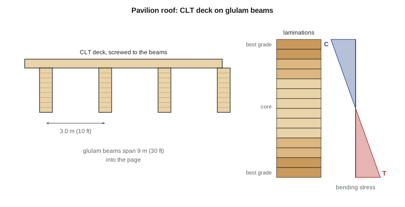
Owen starts from the moment demand. With the self-weight of the beam, about 0.4 kN/m, the factored load is \(w_f = 1.25(1.2 \times 3.0 + 0.46) + 1.5(2.6)(3.0) = 16.8\) kN/m and \(M_f = 170\) kN·m. The required section modulus at \(K_{Zbg} \approx 0.95\) is \(170 \times 10^6/(0.9 \times 30.6 \times 0.95) = 6.5 \times 10^6\) mm³, which a 175 mm wide beam reaches at a depth of about 470 mm. Deflection usually governs long timber roof beams, though, so Sofia runs several sizes.
# Lesson 2: office annex floor joists and the pavilion glulam roof beams (CSA O86)
# --- Joists: S-P-F No.1/No.2 38 x 235 at 300 mm, simple span 4.2 m
fb, fv, E = 11.8, 1.5, 9500.0
b, d, s, L = 38.0, 235.0, 0.300, 4.2
D, LL = 0.7 + 1.0, 2.4                       # kPa: floor dead + partitions, office live
wf = (1.25 * D + 1.5 * LL) * s               # kN/m, case 2
Mf, Vf = wf * L**2 / 8, wf * L / 2
Mr = 0.9 * fb * 1.0 * 1.10 * (b * d**2 / 6) * 1.1 / 1e6     # KD KH, KZb = 1.1
Vr = 0.9 * fv * 1.0 * 1.10 * (2 * b * d / 3) * 1.0 / 1e3    # KZv taken as 1.0 here
I = b * d**3 / 12
dL = 5 * LL * s * (L * 1e3)**4 / (384 * E * I)              # live load, N/mm = kN/m
print(f"Joists: wf = {wf:.2f} kN/m, Mf = {Mf:.2f} vs Mr = {Mr:.2f} kN.m, Vf = {Vf:.2f} vs Vr = {Vr:.2f} kN")
print(f"        live load deflection = {dL:.1f} mm vs L/360 = {L*1e3/360:.1f} mm")

# --- Glulam beams: 24f-EX Douglas fir-larch, span 9.0 m at 3.0 m, CLT roof
fbg, fvg, Eg = 30.6, 2.0, 12800.0
Lg, sg = 9.0, 3.0
Dr, S = 1.2, 2.6                              # kPa: CLT + roofing, snow
print("\nGlulam options (b x d mm):")
for bg, ng in [(175, 13), (175, 14), (175, 15), (215, 13)]:
    dg = 38 * ng
    sw = 4.9 * bg * dg / 1e6                  # self-weight, kN/m (about 500 kg/m3)
    wf = 1.25 * (Dr * sg + sw) + 1.5 * S * sg
    Mf, Vf = wf * Lg**2 / 8, wf * Lg / 2
    KZbg = min(1.0, 1.03 * (bg / 1e3 * Lg) ** -0.18)
    Mr = 0.9 * fbg * 1.0 * (bg * dg**2 / 6) * KZbg / 1e6    # laterally supported by the CLT: KL = 1
    Vr = 0.9 * fvg * 2 * bg * dg / 3 / 1e3
    I = bg * dg**3 / 12
    dS = 5 * S * sg * (Lg * 1e3)**4 / (384 * Eg * I)
    dT = 5 * (Dr * sg + sw + S * sg) * (Lg * 1e3)**4 / (384 * Eg * I)
    ok = "OK" if Mf <= Mr and dS <= Lg * 1e3 / 360 else "NG"
    print(f"  {bg}x{dg}: KZbg {KZbg:.3f}, Mf {Mf:.0f} vs Mr {Mr:.0f} kN.m, Vf {Vf:.0f} vs Vr {Vr:.0f} kN, "
f"snow defl {dS:.0f} mm (L/360 = {Lg*1e3/360:.0f}), total {dT:.0f} mm {ok}")Joists: wf = 1.72 kN/m, Mf = 3.79 vs Mr = 4.49 kN.m, Vf = 3.61 vs Vr = 8.84 kN
live load deflection = 7.5 mm vs L/360 = 11.7 mm
Glulam options (b x d mm):
175x494: KZbg 0.949, Mf 169 vs Mr 186 kN.m, Vf 75 vs Vr 104 kN, snow defl 30 mm (L/360 = 25), total 45 mm NG
175x532: KZbg 0.949, Mf 170 vs Mr 216 kN.m, Vf 75 vs Vr 112 kN, snow defl 24 mm (L/360 = 25), total 36 mm OK
175x570: KZbg 0.949, Mf 170 vs Mr 248 kN.m, Vf 76 vs Vr 120 kN, snow defl 19 mm (L/360 = 25), total 29 mm OK
215x494: KZbg 0.915, Mf 171 vs Mr 220 kN.m, Vf 76 vs Vr 127 kN, snow defl 24 mm (L/360 = 25), total 37 mm OKWorked problem
Selecting the pavilion beam
Select a 24f-EX glulam beam for the 9.0 m span at 3.0 m spacing, checking bending, shear and snow deflection against span/360.
Show solution
- Try 175x532 (14 laminations of 38 mm):
- \[K_{Zbg} = 1.03(0.175 \times 9.0)^{-0.18} = 0.949\]
- \[M_r = 0.9(30.6)\frac{175(532)^2}{6}(0.949) = 216\ \text{kN·m} \ge 170\ \text{kN·m}\]
- \[V_r = 0.9(2.0)\frac{2(175)(532)}{3} = 112\ \text{kN} \ge 75\ \text{kN}\]
- \[\Delta_S = \frac{5(2.6 \times 3.0)(9000)^4}{384(12\,800)(2.20 \times 10^9)} = 24\ \text{mm} \le 25\ \text{mm}\]
Answer: Use 175x532 24f-EX. The 494 mm depth satisfies bending but deflects 30 mm under snow, more than span/360; deflection, not strength, sets the depth. The total load deflection is 36 mm, of which 12 mm is dead load; with creep of that part the long-term sag is about 42 mm, so the beams are cambered about 12 mm, roughly the dead load deflection.
Lateral stability
When the compression edge of a beam is not held in place, the beam can buckle sideways and twist, just like a steel beam. O86 handles this with the lateral stability factor \(K_L\), computed from a slenderness ratio \(C_B = \sqrt{L_e d/b^2}\) that combines the effective unsupported length \(L_e\), depth and width. For \(C_B \le 10\) there is no reduction; above that, \(K_L\) falls, and \(C_B\) may not exceed 50. Glulam beams that are deep and narrow, such as 130x608, are sensitive to lateral buckling during erection, before the deck goes on.
The pavilion beams have a depth-to-width ratio of 3.0, and the CLT deck screwed to their tops braces them in service. During erection, the contractor will set the beams in pairs with temporary bracing until the first CLT panel is fixed, which the drawings will require. Where a beam is cantilevered or continuous over a support, the bottom edge is in compression near the support and needs its own bracing, such as knee braces or blocking fixed to the deck.
Choosing between sawn lumber, engineered lumber and glulam
Sawn lumber is the cheapest structural material per unit of strength for short spans and closely spaced members, and carpenters handle it easily. Depth is limited, though: the deepest common joists are 38x286 (2x12), and long lengths of large sawn timbers are hard to find. Laminated veneer lumber and wood I-joists reach longer spans with uniform properties and little shrinkage. Glulam can be made to almost any size and curved or tapered, which is why it is the natural choice for exposed roof beams and arches. The salt shed's arches and the pavilion beams are glulam for that reason.
Fabrication and handling
Glulam members arrive from the plant cut to length with their holes drilled and their connection hardware often fitted. They are usually wrapped to keep them clean and dry, and the wrap should stay on until the roof is closed in, with slits cut on the underside so condensation can drain. Rough handling with chains or forks damages the edges, so slings are used. On site, glulam must be stored off the ground and covered. Exposed beams in public buildings are often specified with an architectural appearance grade, which controls voids, knots and surface finish.
Common mistakes
MistakeUsing \(K_{Zb}\) for sawn lumber on a glulam beam.
InsteadGlulam uses \(K_{Zbg} = 1.03(BL)^{-0.18}\).
MistakeSizing a long roof beam for bending only.
InsteadDeflection under snow or live load often governs; check it with the actual modulus and span.
MistakeIgnoring creep under permanent load.
InsteadEstimate long-term deflection with a creep factor of about 1.5 to 2 on the permanent part, and camber glulam where needed.
MistakeCutting square notches on the tension side at supports.
InsteadAvoid notches; they start splits. Use tapers or steel seats instead.
Summary and key terms
- Bending: \(M_r = \phi F_b S K_Z K_L\), with \(K_H\) for repetitive members and \(K_{Zbg}\) for glulam.
- Shear: \(V_r = \phi F_v (2A/3)\); check at \(d\) from the support face.
- Deflection often governs long timber beams; creep adds to the long-term deflection.
- Lateral stability depends on the unbraced length, depth and width; decks brace beams in service, but erection needs temporary bracing.
- The annex joists are 38x235 at 300 mm (0.84 in bending), and the pavilion beams are 175x532 24f-EX, governed by snow deflection.
- Laterally supported
- Having the compression edge held against sideways movement, usually by a deck or sheathing.
- Glulam size factor
- KZbg = 1.03(BL)^-0.18, which reduces bending strength for large glulam beams.
- Creep
- The slow increase in deformation of wood under sustained load.
- Camber
- An upward curve built into a glulam beam to offset dead load deflection.
- Longitudinal shear
- Sliding of wood fibres past each other along the grain.
- Stress grade
- A designation of glulam strength and layup, such as 24f-EX or 24F-V4.
- Bearing length
- The length of a beam in contact with its support.
- Unbalanced layup
- A glulam layup with higher grade laminations at the tension face than at the compression face.
Practice problems
Work each problem on paper first, then reveal the answer to check.
A 38x184 S-P-F joist at 400 mm spans 3.6 m under the same floor loads. Find \(M_f\) and \(M_r\) (\(K_{Zb} = 1.2\)).
Show answer
\(w_f = 5.73(0.4) = 2.29\) kN/m; \(M_f = 3.71\) kN·m. \(S = 214 \times 10^3\) mm³, \(M_r = 0.9(12.98)(214 \times 10^3)(1.2) = 3.00\) kN·m, so it fails.
Why is the snow deflection limit tighter for the pavilion than for a typical roof?
Show answer
Glazing under the beam ends and at the clerestory would crack or leak if the roof deflected too much.
Find \(K_{Zbg}\) for a 215 mm wide glulam beam 12 m long.
Show answer
\(1.03(0.215 \times 12)^{-0.18} = 0.87\).
What does the contractor need to do before the CLT is fixed to the beams?
Show answer
Brace the beams laterally, because until the deck is attached their compression edges are unsupported.
Lesson quiz · 5 questions
Score 60% or more to complete this lesson.
Create a free account to save your progress, take quizzes and earn a certificate.