
CIV-421 · Lesson 10 of 12 · 19 min
Masonry shear walls
Masonry walls are very stiff in their own plane, and in many buildings they are the whole lateral system. At the operations centre, the wash bay is a concrete block addition on the east end of the steel-framed garage, and its two end walls, each 7.2 m long and 6.0 m high, will replace the steel X-bracing in the end bay of the garage that CIV-331 designed. The roof diaphragm of the garage delivers a factored wind shear of 150 kN to each wall. This lesson designs those walls for in-plane shear and flexure.
How shear walls behave
A masonry shear wall loaded in its plane is a deep cantilever. Depending on its aspect ratio, reinforcement and axial load, it fails in one of three main ways. A squat wall with little vertical load tends to fail in shear, with diagonal cracks running from corner to corner through the units and joints. A taller, slender wall tends to fail in flexure, with the vertical bars at the heel yielding and the toe crushing. A lightly loaded wall without enough dowels can slide on a bed joint or at its base. The flexural mode is ductile and is the mode designers want; the shear mode is brittle.
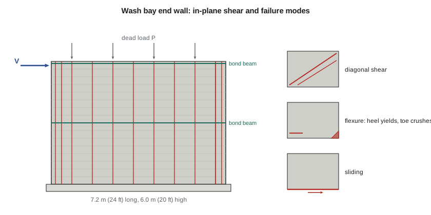
Shear resistance
S304 gives the factored in-plane shear resistance as the sum of a masonry contribution, including a share of the axial compression, and a steel contribution from horizontal reinforcement:
Here \(d_v\) is the effective depth for shear, taken as 0.8 times the wall length; \(P_d\) the axial compression, using 0.9 of the dead load; \(b_w\) the wall thickness; and \(\gamma_g\) a factor of 1.0 for fully grouted walls and 0.5 for partially grouted walls, which reflects their lower and less reliable shear capacity. The ratio \(M_f/(V_fd_v)\) is limited to between 0.25 and 1.0: squat walls get more masonry shear strength than slender ones because more of the shear goes directly to the base in a diagonal strut. The steel term uses 0.60 of the yield force of the horizontal bars crossing a diagonal crack. An upper limit on the total protects against crushing of the diagonal strut.
Flexure in the plane of the wall
The overturning moment at the base of the wall is resisted by the vertical bars on the tension side and the masonry compression at the toe, with the axial load helping. With bars distributed along the length, an exact calculation uses strain compatibility, like a reinforced concrete column with many layers of steel. For walls with uniformly distributed bars and moderate axial load, a simple and widely used approximation is
where \(A_s\) is the total vertical steel, \(\omega = A_sf_y/(l_wtf'_m)\) and \(\alpha = P/(l_wtf'_m)\), with resistance factors applied to the materials as the standard requires. It assumes that all the bars in tension yield. A designer who wants more precision runs a strain compatibility calculation, which Sofia's script could do with a few more lines.
The wash bay end wall
The wall is 190 mm block, partially grouted, with 15M vertical bars at 800 mm and two extra 15M bars in the end cores at each end, and 15M horizontal bars in bond beams every 1200 mm (six courses). \(f'_m = 10\) MPa and \(f_y = 400\) MPa. The roof and the wall itself give a dead load on the wall of 3.6 kN/m from the roof and 2.6 kPa of wall area.
# Lesson 10: in-plane shear wall, wash-bay end wall, 190 mm block, lw 7.2 m, h 6.0 m (S304 format)
import math
lw, h, t, fs_t = 7200.0, 6000.0, 190.0, 32.0
fm, fy = 10.0, 400.0
phim, phis = 0.60, 0.85
Vf = 150.0                                     # kN, factored wind at roof level
Mf = Vf * h / 1e3                              # kN.m at the base
Pd = 0.9 * (3.6 * lw / 1e3 + 2.6 * h / 1e3 * lw / 1e3)   # 0.9 x dead load on the wall (kN)
dv = max(0.8 * lw, 0.0)
ratio = min(max(Mf * 1e3 / (Vf * dv), 0.25), 1.0)
vm = 0.16 * (2 - ratio) * math.sqrt(fm)
bw = t                                         # overall thickness; gamma_g allows for partial grouting
gamma_g = 0.5                                  # partially grouted wall
Vm = phim * (vm * bw * dv + 0.25 * Pd * 1e3) * gamma_g / 1e3
Av, s = 200.0, 1200.0                          # 15M horizontal bar in a bond beam every 1200 mm
Vs = phis * 0.60 * Av * fy * dv / s / 1e3
Vmax = 0.4 * phim * math.sqrt(fm) * bw * dv * gamma_g / 1e3
Vr = min(Vm + Vs, Vmax)
print(f"Mf = {Mf:.0f} kN.m, Pd = {Pd:.0f} kN, dv = {dv:.0f} mm, M/(V dv) = {ratio:.2f}")
print(f"vm = {vm:.3f} MPa, bw = {bw:.0f} mm, Vm = {Vm:.0f} kN, Vs = {Vs:.0f} kN, upper limit {Vmax:.0f} kN")
print(f"Vr = {Vr:.0f} kN vs Vf = {Vf:.0f} kN, ratio {Vf/Vr:.2f}")

# In-plane flexure: distributed 15M @ 800 plus 2-15M at each end (approximate design equation)
As_total = 200 * (lw / 800 - 1) + 4 * 200
w_ = phis * As_total * fy / (lw * t * phim * fm)
alpha = Pd * 1e3 / (lw * t * phim * fm)
c_lw = (w_ + alpha) / (2 * w_ + 0.85 * 0.8)
Mr = 0.5 * phis * As_total * fy * lw * (1 + Pd * 1e3 / (phis * As_total * fy)) * (1 - c_lw) / 1e6
print(f"As = {As_total:.0f} mm2, c/lw = {c_lw:.3f}, Mr = {Mr:.0f} kN.m vs Mf = {Mf:.0f} kN.m, ratio {Mf/Mr:.2f}")Mf = 900 kN.m, Pd = 124 kN, dv = 5760 mm, M/(V dv) = 1.00 vm = 0.506 MPa, bw = 190 mm, Vm = 175 kN, Vs = 196 kN, upper limit 415 kN Vr = 371 kN vs Vf = 150 kN, ratio 0.40 As = 2400 mm2, c/lw = 0.130, Mr = 2944 kN.m vs Mf = 900 kN.m, ratio 0.31
Worked problem
Shear design of the wash bay wall
Check the in-plane shear of the 7.2 m by 6.0 m wall for \(V_f = 150\) kN at the top.
Show solution
- \[M_f = 150(6.0) = 900\ \text{kN·m} \qquad d_v = 0.8(7200) = 5760\ \text{mm} \qquad \frac{M_f}{V_fd_v} = 1.04 \to 1.0\]
- \[v_m = 0.16(2 - 1.0)\sqrt{10} = 0.506\ \text{MPa} \qquad P_d = 0.9[3.6(7.2) + 2.6(6.0)(7.2)] = 124\ \text{kN}\]
- \[V_m = 0.60[0.506(190)(5760) + 0.25(124\,000)](0.5) = 175\ \text{kN}\]
- \[V_s = 0.85(0.60)(200)(400)\frac{5760}{1200} = 196\ \text{kN}\]
- \[V_r = 175 + 196 = 371\ \text{kN} \le 415\ \text{kN (upper limit)} \qquad \frac{V_f}{V_r} = 0.40\]
Answer: The wall has ample shear capacity, at a ratio of 0.40, and in-plane flexure is at 0.31. The horizontal steel contributes more than half the resistance, which is typical of partially grouted walls with the 0.5 grouting factor on the masonry term. With a factored wind shear this low compared with the capacity, minimum reinforcement and detailing, not strength, set the design.
Minimum reinforcement and detailing
Because the wind shear is small, the reinforcement in the wash bay walls is set mostly by minimum requirements and good practice. Vertical bars go at every corner, at each side of every opening, at the ends of each wall and at regular spacing between, so that every part of the wall can span to a bar. Horizontal reinforcement goes in a bond beam at the roof, at each floor or lintel level and at regular spacing, or as joint reinforcement in the bed joints. S304 sets minimum areas and maximum spacings that depend on the seismic hazard and on whether the wall is part of the lateral system; even in low-hazard regions, a minimum amount of reinforcement controls cracking and gives the wall some ability to redistribute load if it is damaged.
The same thinking applies to the pump house. Its walls are short and stiff in plane, and the wind on the building is small, so their in-plane shear capacity is many times the demand. The team checks it quickly, confirms that the bars already chosen for out-of-plane bending satisfy the minimums, and adds two bars at each door jamb and corner. Most of the design effort in a small masonry building goes into openings, lintels, corners, bearings and the connection to the roof, not into the shear calculation.
Sliding and the base connection
The shear must pass from the wall into the foundation. Friction under the dead load carries some of it, but for a lightly loaded wall the dowels from the footing into the grouted cores do most of the work in shear friction. The dowels lap with the vertical bars of the wall, so they also anchor the tension side for overturning. At the top, the roof diaphragm delivers the shear through anchor bolts or welded plates into the bond beam, and the bond beam acts as a collector along the wall. The wash bay walls share the steel garage's end bay, so the connection between the steel roof and the masonry wall must allow the steel frame to move with temperature while transferring shear, which slotted connections in the direction of the wall achieve.
Stiffness and load sharing
When several walls resist lateral load together through a rigid diaphragm, they share the load in proportion to their stiffness. A masonry wall's stiffness depends on both flexure and shear deformation and on whether it is cracked; squat walls are much stiffer than slender piers, and a wall with a large opening behaves as two piers with a coupling beam. Long walls attract most of the load. Where a stiff masonry wall and a flexible steel frame share the load, as in the garage, the masonry takes almost all of it until it cracks, which is why the design gives the wash bay walls the full end-bay shear and does not count on the steel frame at all.
For a cantilever wall of height \(h\), the lateral stiffness combines bending and shear deformation:
For the wash bay wall, whose height is less than its length, the shear term is about as large as the bending term, and the uncracked wall is roughly ten times stiffer than the X-braced steel bay it replaces. Cracking reduces the stiffness of masonry walls considerably, so designers who need to distribute load between walls of different types often use cracked or effective stiffness values, typically a half or less of the uncracked value.
Earthquake design and ductility
Thunder Bay and Duluth have low seismic hazard, and wind governs. In regions of higher hazard, masonry shear walls are classified by their ductility. The NBC assigns force modification factors from conventional construction (\(R_d = 1.5\)) through moderately ductile (\(R_d = 2.0\)) to ductile shear walls (\(R_d = 3.0\)), and S304 attaches detailing requirements to each class: minimum reinforcement, maximum bar spacing, limits on the compression zone, and capacity design so that flexural yielding occurs before shear failure. Unreinforced masonry is not permitted for the lateral system in regions of moderate and high hazard.
Unreinforced masonry buildings are among the most vulnerable structures in earthquakes, and many older ones in North American cities have been strengthened with steel frames, reinforced cores or fibre-reinforced overlays. The lesson for new design is that reinforcement, grouting and good connections to floors and roofs make masonry a reliable lateral system; their absence makes it a hazard.
Common mistakes
MistakeUsing the gross wall thickness and full grouting factor for a partially grouted wall.
InsteadApply \(\gamma_g = 0.5\) for partially grouted walls.
MistakeUsing the full dead load to help shear and overturning resistance.
InsteadUse 0.9D (or 0.6D in some combinations) so that dead load is not overestimated.
MistakeDesigning the wall but not the base and top connections.
InsteadDowels, anchor bolts and the bond beam collector must carry the full shear and overturning.
MistakeAllowing a brittle shear failure before flexural yielding in seismic design.
InsteadProvide shear strength greater than the shear associated with flexural strength in ductile walls.
Summary and key terms
- In-plane shear walls fail in shear, flexure or sliding; flexural yielding is the ductile mode.
- \(V_r = \phi_m(v_mb_wd_v + 0.25P_d)\gamma_g + \phi_s(0.60A_vf_yd_v/s)\), with \(v_m = 0.16(2 - M_f/V_fd_v)\sqrt{f'_m}\) and \(\gamma_g = 0.5\) for partial grouting.
- In-plane flexure with distributed bars can be estimated with \(M \approx \frac12A_sf_yl_w(1 + P/A_sf_y)(1 - c/l_w)\).
- The wash bay wall: \(V_r = 371\) kN against 150 kN (0.40) and in-plane flexure at 0.31.
- Seismic detailing and capacity design make masonry shear walls ductile.
- In-plane shear
- Shear acting parallel to the face of a wall.
- Shear friction
- Transfer of shear across a crack or joint by friction and dowel clamping.
- Grouting factor
- A factor that reduces the shear strength of partially grouted walls.
- Diagonal tension cracking
- Cracking across a wall at an angle, caused by in-plane shear.
- Toe crushing
- Crushing of the masonry at the compression end of a wall in flexure.
- Capacity design
- Design that ensures a ductile mode forms before brittle modes.
- Pier
- A narrow segment of wall between openings.
- Collector
- An element that gathers diaphragm shear and delivers it to a wall.
Practice problems
Work each problem on paper first, then reveal the answer to check.
Why do squat walls have higher masonry shear strength per unit area than slender walls?
Show answer
More of the shear goes directly to the base in a diagonal compression strut.
If the wall were fully grouted, what would the masonry contribution become?
Show answer
With \(\gamma_g = 1.0\), \(V_m = 351\) kN, and with \(V_s = 196\) kN the total would be about 547 kN, below the upper limit of about 830 kN.
Why is 0.9D used rather than the full dead load in the shear and overturning checks?
Show answer
Dead load helps resist shear and overturning, so a lower value is conservative.
A wall has a large door opening near one end. How does that change its behaviour?
Show answer
It becomes a pier and a short wall segment linked by a lintel, with much lower stiffness and capacity than the solid wall.
Lesson quiz · 5 questions
Score 60% or more to complete this lesson.
Create a free account to save your progress, take quizzes and earn a certificate.