
CIV-321 · Lesson 8 of 12 · 24 min
Approximate methods and influence lines for indeterminate structures
Exact methods need member sizes, because indeterminate structures share load by stiffness. At the start of a design the sizes are not yet known. Engineers break this circle with approximate methods: assumptions about where the moment is zero, or how the shear divides, that make the structure determinate. The results are good enough to size members, which can then be checked by an exact analysis. The second half of this lesson turns to moving and variable loads. Influence lines for indeterminate structures are curved, but the Müller-Breslau principle from CIV-224 still gives their shape at a glance, and that shape tells you where to put the load.
Approximate analysis for gravity load
Each assumption about a point of zero moment in a beam removes one unknown. For a beam continuous at both ends under uniform load, the exact inflection points of a fixed-fixed beam lie at \(0.211L\) from each end (lesson 2). Real beams in frames have ends that are neither pinned nor fixed, so a common approximation places the inflection points at \(0.1L\) from each end. The central \(0.8L\) is then a simple beam and the end portions are cantilevers carrying its reactions.
These bracket the true values. A fixed-fixed beam has \(0.042wL^2\) at midspan and \(-0.083wL^2\) at its ends; a simple beam has \(0.125wL^2\) at midspan and nothing at its ends. Concrete design standards formalize a similar idea through tabulated moment coefficients for continuous beams and slabs with regular spans, such as \(wL^2/14\) for the positive moment in an end span built integrally with its support and \(wL^2/9\) for the negative moment at the first interior support of a two-span beam. They are calibrated to cover pattern loading, so they apply only within stated limits on span ratios and live-to-dead load ratios.
The portal method for lateral load
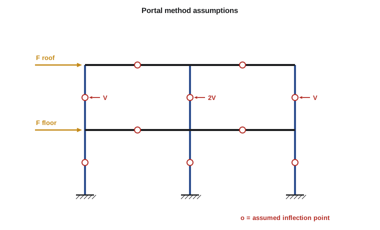
Lesson 6 showed that, in an unbraced frame under lateral load, columns and beams bend in double curvature with inflection points near their middles. The portal method, developed for the early steel skyscrapers, makes three assumptions:
- There is an inflection point at mid-height of every column.
- There is an inflection point at midspan of every beam.
- In each storey, each interior column carries twice the shear of each exterior column, because an interior column acts as part of two adjacent portals.
With these assumptions the frame becomes determinate. The procedure is mechanical: find the shear in each storey from the loads above it, divide it among the columns, multiply each column shear by half its height to get its end moments, then use joint equilibrium from left to right to find the beam end moments, and beam shears to find the column axial forces.
Worked problem
Office wing frame by the portal method
The office wing frame is two bays of 7.5 m and two storeys of 4.0 m. Factored wind loads are 20.0 kN at the roof and 36.0 kN at the second floor. Find the column moments, the second-floor beam moments and the axial force in the exterior ground-storey columns.
Show solution
- Upper storey shear: 20.0 kN. With shares 1 : 2 : 1, the exterior columns carry 5.0 kN and the interior column 10.0 kN. Column end moments: \(5.0(2.0) = 10.0\) and \(10.0(2.0) = 20.0\ \text{kN·m}\).
- Ground storey shear: \(20.0 + 36.0 = 56.0\) kN. Exterior columns 14.0 kN, interior 28.0 kN; moments \(28.0\) and \(56.0\ \text{kN·m}\).
- Roof beams: the exterior joint has only the upper column below it, so the beam end moment is 10.0 kN·m; the beam shear is \(2(10.0)/7.5 = 2.67\) kN.
- Second-floor beams: at the exterior joint the beam balances the columns above and below, \(10.0 + 28.0 = 38.0\ \text{kN·m}\). At the interior joint, \(20.0 + 56.0 = 76.0\) kN·m is shared by two beams, 38.0 each. Beam shear \(2(38.0)/7.5 = 10.13\) kN.
- Exterior column axial force in the ground storey: the sum of the beam shears above, \(2.67 + 10.13 = 12.8\) kN, tension on the windward side and compression on the leeward side. The interior column carries no axial force from wind.
Answer: The governing wind moments are 56.0 kN·m in the interior ground-storey column and 38.0 kN·m at the ends of the second-floor beams. These are adequate for preliminary sizing; lesson 11 checks the frame by the stiffness method.
The cantilever method
For tall, slender frames, where overall bending of the building dominates, the cantilever method gives better results. It keeps the inflection-point assumptions but replaces the shear rule with an axial rule: the column axial forces vary linearly with distance from the centroid of the column areas, as the fibre stresses do in a cantilever beam. Taking moments of the storey loads about the inflection points of each level then gives the axial forces, from which beam shears and moments follow.
For the office wing frame, with equal column areas, the centroid is at the interior column, which therefore carries no axial force. At mid-height of the ground storey the overturning moment is \(20.0(6.0) + 36.0(2.0) = 192\ \text{kN·m}\), giving exterior column forces of \(192/(2 \times 7.5) = 12.8\) kN, identical to the portal result. For this symmetric low-rise frame the two methods agree; they diverge for tall frames and for unequal bays.
| Method | Assumptions | Best suited to |
|---|---|---|
| Inflection points at 0.1L | Zero moment near the ends of beams under gravity load | Preliminary beam sizing |
| Code moment coefficients | Tabulated coefficients covering pattern loads | Regular continuous beams and slabs |
| Portal method | Inflection points at mid-members; interior columns take twice the exterior shear | Low-rise unbraced frames |
| Cantilever method | Inflection points at mid-members; column axial force proportional to distance from centroid | Tall, slender unbraced frames |
Influence lines for indeterminate structures
An influence line shows how a response at one point (a reaction, shear or moment) varies as a unit load moves across the structure. In CIV-224 the Müller-Breslau principle gave influence lines for determinate structures as straight-line mechanisms. The principle holds equally for indeterminate structures: the influence line for a response is the deflected shape of the structure when the restraint corresponding to that response is removed and a unit displacement is imposed in its place. The difference is that the remaining structure is still indeterminate, so the deflected shape is a smooth curve rather than a set of straight lines.
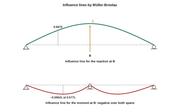
For the reaction at an interior support B of a two-span continuous beam with equal spans L, removing the support and pushing B up by one unit gives the curve
and its mirror image in the second span. At midspan of the first span \(a = L/2\) the ordinate is \(11/16 = 0.6875\): a load there sends more than two thirds of itself to B. For the moment at B, inserting a hinge and rotating the two sides by a unit relative angle gives
which is negative everywhere: load anywhere on either span causes hogging at B. Its largest magnitude is \(0.0962L\) at \(a = L/\sqrt{3} = 0.577L\).
| a / L in span 1 | 0.1 | 0.2 | 0.3 | 0.4 | 0.5 | 0.6 | 0.7 | 0.8 | 0.9 |
|---|---|---|---|---|---|---|---|---|---|
| \(R_A\) | 0.875 | 0.752 | 0.632 | 0.516 | 0.406 | 0.304 | 0.211 | 0.128 | 0.057 |
| \(R_B\) | 0.150 | 0.296 | 0.437 | 0.568 | 0.688 | 0.792 | 0.879 | 0.944 | 0.986 |
| \(M_B / L\) | −0.025 | −0.048 | −0.068 | −0.084 | −0.094 | −0.096 | −0.089 | −0.072 | −0.043 |
Worked problem
The access road girder as a two-span beam
The access road bridge is being considered as a two-span continuous girder with spans of 20.0 m. Find the largest hogging moment over the pier B from a single 140 kN axle, and from a uniform lane load of 10.0 kN/m placed to maximize it.
Show solution
- Single axle: place it at the peak of the influence line, \(a = 0.577L = 11.5\) m. Ordinate \(-0.0962(20.0) = -1.925\) m.
- \[M_B = 140(-1.925) = -269\ \text{kN·m}\]
- Uniform load: the influence line is negative over both spans, so load both. The area under the curve in one span is
- \[\int_0^L \frac{a(L^2 - a^2)}{4L^2}\,da = \frac{L^2}{16}\]
- \[M_B = -w\,\Big(2 \times \frac{L^2}{16}\Big) = -\frac{wL^2}{8} = -\frac{10.0(20.0)^2}{8} = -500\ \text{kN·m}\]
Answer: The axle alone gives \(-269\) kN·m when placed at 11.5 m from the abutment, and the lane load on both spans gives \(-500\) kN·m; the design value combines them as the bridge code specifies. The result \(-wL^2/8\) for full load on two spans is the classic two-span value, here confirmed from the influence line area.
Qualitative influence lines and pattern loading
Often only the shape matters. Sketching the Müller-Breslau curve for a response tells you which spans to load for its maximum, without computing a single ordinate. For the sagging moment at the middle of a span, insert a hinge there and bend the beam: the curve is positive in that span, negative in the adjacent spans and positive again in the spans beyond. Hence the rule from lesson 2: load the span and every second span from it. For the hogging moment over a support, the curve is negative in the two adjacent spans and positive in the next ones. The same sketches applied to a multi-storey frame give the checkerboard live load patterns used for the maximum beam moments in buildings.
Solving it in code
The program applies the portal method to any regular frame: give it the bay widths, the tier heights and the lateral loads. Its column, beam and axial results reproduce the hand calculation, and adding a third bay or a third level shows how quickly the method scales.
# Portal method for a regular unbraced frame under lateral load
# Assumptions: inflection points at mid-height of columns and midspan of beams;
# interior columns carry twice the shear of exterior columns in each tier of columns.
bays = [7.5, 7.5]                  # bay widths (m)
heights = [4.0, 4.0]               # column tier heights from the top down (m)
F = [20.0, 36.0]                   # lateral loads at each level from the roof down (kN)

ncol = len(bays) + 1
shares = [1.0 if c in (0, ncol - 1) else 2.0 for c in range(ncol)]
col_moment = []                    # column end moments, tier by tier
tier_shear = 0.0
for s, h in enumerate(heights):
    tier_shear += F[s]
    V = [tier_shear * k / sum(shares) for k in shares]
    Mc = [v * h / 2 for v in V]
    col_moment.append(Mc)
    print("tier %d (from top): shear %.1f kN, column shears %s kN, column moments %s kN*m"
          % (s + 1, tier_shear, [round(v, 2) for v in V], [round(m, 2) for m in Mc]))

axial = [0.0] * ncol
for s in range(len(heights)):
    # joint equilibrium from left to right: beam moment = column moments above and below minus beam on the left
    above = col_moment[s - 1] if s > 0 else [0.0] * ncol
    below = col_moment[s]
    left = 0.0; beamM = []
    for c in range(ncol - 1):
        m = above[c] + below[c] - left
        beamM.append(m); left = m
    beamV = [2 * m / b for m, b in zip(beamM, bays)]
    # beam shears accumulate as column axial forces (tension on the windward side)
    for c in range(ncol):
        if c > 0: axial[c] -= beamV[c - 1]
        if c < ncol - 1: axial[c] += beamV[c]
    print("level %d beams: end moments %s kN*m, shears %s kN; column axial below %s kN"
% (s + 1, [round(m, 2) for m in beamM], [round(v, 2) for v in beamV], [round(a, 2) + 0.0 for a in axial]))tier 1 (from top): shear 20.0 kN, column shears [5.0, 10.0, 5.0] kN, column moments [10.0, 20.0, 10.0] kN*m tier 2 (from top): shear 56.0 kN, column shears [14.0, 28.0, 14.0] kN, column moments [28.0, 56.0, 28.0] kN*m level 1 beams: end moments [10.0, 10.0] kN*m, shears [2.67, 2.67] kN; column axial below [2.67, 0.0, -2.67] kN level 2 beams: end moments [38.0, 38.0] kN*m, shears [10.13, 10.13] kN; column axial below [12.8, 0.0, -12.8] kN
Approximate methods earn their place in modern practice as checks: if a computer model's column moments under wind differ from the portal estimate by more than about 30 per cent for a regular frame, it is worth finding out why before trusting either.
Common mistakes
MistakeUsing approximate results for final design without an exact check.
InsteadUse them to size members and to check computer output; confirm with an exact analysis.
MistakeApplying the portal method to frames with very unequal bays or tall, slender proportions.
InsteadUse the cantilever method for slender frames, and an exact analysis for irregular ones.
MistakeDrawing indeterminate influence lines as straight lines.
InsteadRemoving one restraint from an indeterminate structure leaves a structure that bends: the curve is smooth.
MistakeLoading every span for the maximum span moment of a continuous beam.
InsteadLoad the span and alternate spans, as the qualitative influence line shows.
Summary and key terms
- Approximate methods make a structure determinate by assuming inflection points or force distributions.
- Portal method: inflection points at mid-members; interior columns take twice the exterior shear.
- Cantilever method: column axial forces proportional to distance from the centroid.
- Müller-Breslau applies to indeterminate structures, giving curved influence lines.
- Two equal spans: \(R_B\) ordinate 0.6875 at midspan; \(M_B\) peak \(-0.0962L\) at 0.577L; full uniform load \(M_B = -wL^2/8\).
- Approximate analysis
- An analysis made determinate by assumptions about the distribution of forces.
- Portal method
- An approximate method for lateral load on low-rise frames based on mid-member inflection points and a 1 : 2 shear split.
- Cantilever method
- An approximate method for lateral load on tall frames treating the building as a vertical cantilever.
- Influence line
- A graph of a response at one point as a unit load moves across the structure.
- Müller-Breslau principle
- The influence line for a response is the deflected shape produced by releasing that restraint and imposing a unit displacement.
- Checkerboard loading
- Live load placed on alternate panels of a frame to maximize beam moments.
- Moment coefficient
- A tabulated multiplier of wL squared for design moments in regular continuous members.
Practice problems
Work each problem on paper first, then reveal the answer to check.
Using inflection points at 0.1L, estimate the end and midspan moments of an interior beam with \(wL^2 = 400\) units.
Show answer
Midspan \(0.080(400) = 32\); ends \(-0.045(400) = -18\).
In the portal method, why does an interior column take twice the shear of an exterior column?
Show answer
It acts as a leg of two adjacent portals, while an exterior column belongs to only one.
A one-storey, three-bay frame carries 60 kN at the roof. Find the portal method column shears.
Show answer
Shares 1 : 2 : 2 : 1 total 6: exterior 10 kN, interior 20 kN.
What is the influence line ordinate for \(R_B\) of a two-span beam when the load is at 0.8L in span 1?
Show answer
0.944.
Which spans of a four-span beam should be loaded for maximum hogging over the second support?
Show answer
Spans 1 and 2, plus span 4.
Why is the influence line for moment at an interior support of a two-span beam negative everywhere?
Show answer
Rotating the two sides of a hinge at B against each other lifts both spans above the axis in the hogging sense; load anywhere causes hogging at B.
Lesson quiz · 5 questions
Score 60% or more to complete this lesson.
Create a free account to save your progress, take quizzes and earn a certificate.