
CIV-321 · Lesson 6 of 12 · 23 min
Slope-deflection for frames with sway
In a continuous beam the joints rotate but do not translate. In a frame they may also move sideways. A frame braced by walls or diagonal bracing is prevented from swaying, and slope-deflection proceeds exactly as for beams, with one rotation unknown per rigid joint. An unbraced frame, which relies on the bending stiffness of its beams and columns to resist lateral load, sways, and the sway adds new unknowns and new equations. This lesson analyses the garage end frames, which have moment-resisting connections and fixed bases, under wind and roof load.
When does a frame sway?
A frame sways whenever its joints can translate without stretching any member. Treating members as inextensible (lesson 3), a single-bay portal frame has one independent sway: both corners move sideways by the same amount \(\Delta\) because the beam does not change length. A frame with several storeys has one sway per storey, and a frame with sloping members (a gable frame) has additional, coupled sways. To count the independent sways, replace every rigid joint and fixed support with a pin and count the degrees of freedom of the resulting linkage: each is an independent sway.
Sway occurs under lateral load, of course, but also under gravity load whenever the frame or its loading is unsymmetric. An unsymmetric roof load, a frame with columns of different heights or stiffness, or a single heavy load placed eccentrically all produce sideways movement. A braced frame has its sways prevented by the bracing; the bracing then carries the force that would otherwise cause sway.
Equations for a swaying frame
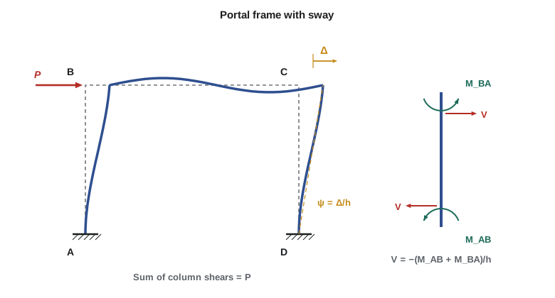
The sway enters the slope-deflection equations of the columns through the chord rotation \(\psi = \Delta/h\), clockwise positive. The beam's chord does not rotate, because both its ends move sideways by the same amount. With one more unknown we need one more equation, and it comes from horizontal equilibrium of the whole storey: the shears at the tops of the columns must balance the lateral load applied above the column bases.
For a column with no load along its height, the shear follows from a free body of the column: \(V = -(M_{\text{top}} + M_{\text{bottom}})/h\), with the moments clockwise positive and V positive acting to the left at the top. The storey shear equation for a single-bay portal with lateral load P to the right at roof level is
If a column carries a lateral load along its height (wind on the wall girts, for example), its free body includes that load, and the shear at its top changes accordingly. If the columns have different heights, each has its own \(\psi = \Delta/h_i\) and its own shear term; the common unknown is \(\Delta\).
The garage end frame under wind
Worked problem
Fixed-base portal frame under lateral load
A garage end frame has fixed bases A and D, columns 6.0 m high and a beam of 18.0 m span with twice the second moment of area of the columns. A factored wind load of 30.0 kN acts to the right at roof level. Find the end moments and the sway if the columns have \(EI = 40\,000\ \text{kN·m}^2\).
Show solution
- Unknowns: \(\theta_B\), \(\theta_C\) and \(\psi\). There are no span loads, so all fixed-end moments are zero.
- Member stiffness factors \(2EI/L\), in units of \(EI_c\): columns \(2/6.0 = 0.3333\); beam \(2(2)/18.0 = 0.2222\).
- \[M_{AB} = 0.3333(\theta_B - 3\psi) \qquad M_{BA} = 0.3333(2\theta_B - 3\psi) \qquad M_{BC} = 0.2222(2\theta_B + \theta_C)\]
- and similarly for \(M_{CB}\), \(M_{CD}\) and \(M_{DC}\).
- The frame and load are antisymmetric in the sense that \(\theta_B = \theta_C = \theta\) (both corners rotate clockwise by the same amount). Joint B equilibrium, \(M_{BA} + M_{BC} = 0\), and the storey shear equation then give two equations in \(\theta\) and \(\psi\):
- \[1.3333\theta - 1.0\psi = 0 \qquad \frac{2\big(0.3333(3\theta - 6\psi)\big)}{6.0} + 30.0 = 0\]
- Solving: \(EI_c\theta = 54.0\) and \(EI_c\psi = 72.0\ \text{kN·m}^2\).
- \[M_{AB} = M_{DC} = -54.0 \qquad M_{BA} = M_{CD} = -36.0 \qquad M_{BC} = M_{CB} = +36.0\ \text{kN·m}\]
- Sway: \(\Delta = \psi h = 72.0(6.0)/40\,000 = 0.0108\) m, or 10.8 mm.
Answer: Each column carries half the wind, 15.0 kN of shear, with 54.0 kN·m at its base and 36.0 kN·m at its top; the beam has 36.0 kN·m at each end, of opposite sense, so it bends in double curvature with a point of contraflexure at midspan. The inflection points in the columns are at \(54/15 = 3.6\) m above the bases, not at mid-height, because the beam is not rigid enough to fix the column tops. The sway of 10.8 mm is about \(h/560\).
The location of the column inflection points is worth noticing. With an infinitely stiff beam the column tops could not rotate, and the inflection points would sit exactly at mid-height. With a flexible beam they move up toward the beam. Lesson 8 uses this observation to build the portal method, an approximate analysis that assumes inflection points at mid-height of columns and midspan of beams.
Pinned bases: the effect of base fixity
If the same frame had pinned bases, the modified slope-deflection equation would apply to each column, the base moments would be zero, and each column would have to carry its 15.0 kN shear by bending over its full height: the corner moments become \(15.0(6.0) = 90.0\ \text{kN·m}\). The sway rises to \(EI_c\psi = 315\), a deflection of 47.3 mm, more than four times the fixed-base value. Base fixity therefore buys a great deal of lateral stiffness, which is why unbraced frames in drift-sensitive buildings often have fixed bases, at the cost of larger footings that can resist moment.
Gravity load and superposition
Under the uniform roof load, a symmetric frame does not sway: \(\theta_C = -\theta_B\) and \(\psi = 0\). The analysis is then a no-sway problem with two rotation unknowns, which symmetry reduces to one.
Worked problem
Combining roof load and wind
The same fixed-base frame carries a factored roof load of 12.0 kN/m on the beam together with the 30.0 kN wind. Find the corner moments.
Show solution
- Roof load alone: \(\text{FEM}_{BC} = -12.0(18.0)^2/12 = -324.0\) kN·m. With \(\theta_C = -\theta_B\) and \(\psi = 0\), joint B gives \(0.6667\theta_B + 0.2222\theta_B - 324.0 = 0\), so \(EI_c\theta_B = 364.5\).
- \[M_{BA} = 0.3333(2)(364.5) = 243.0 \qquad M_{AB} = 121.5\ \text{kN·m}\]
- Superpose the wind results: corner B, \(243.0 - 36.0 = 207.0\); corner C, \(243.0 + 36.0 = 279.0\ \text{kN·m}\). Bases: A, \(121.5 - 54.0 = 67.5\); D, \(121.5 + 54.0 = 175.5\ \text{kN·m}\) (magnitudes).
Answer: The leeward corner C governs at 279.0 kN·m and the leeward base D at 175.5 kN·m. The midspan moment of the beam under roof load is \(486.0 - 243.0 = 243.0\ \text{kN·m}\), which the wind does not change because its beam moment is zero at midspan.
Superposition is valid because the analysis is linear. In design it is applied with the factors of each load combination: lesson 12 returns to this when the full model is set up. For tall or heavily loaded frames, the sway itself increases the moments (the P-delta effect), and superposition of separate first-order results is no longer exact. Both design standards require second-order effects to be considered for unbraced frames, usually by amplifying the first-order sway moments or by a second-order computer analysis.
Multi-storey frames
For a frame of several storeys, each storey has its own sway \(\Delta_i\) and its own storey shear equation: the sum of the column shears just below floor i equals the total lateral load above that level. The office wing, if built as an unbraced two-storey, two-bay frame, would have six joint rotations and two sways, eight unknowns in all. That is about the practical limit for hand solution, and it is where moment distribution (lesson 7), approximate methods (lesson 8) and the matrix stiffness method (lessons 9 to 11) take over.
Solving it in code
Sofia's frame program writes the two joint equations and the storey shear equation as residual functions, builds the coefficient matrix by evaluating them for unit values of each unknown (valid because they are linear), and solves by Gaussian elimination. Set fixed_bases to False to reproduce the pinned-base results, or change Ic_right to see how an unsymmetric frame sways even under roof load alone.
# Slope-deflection for a single-bay portal frame with sway (bases A and D, corners B and C)
# Unknowns: EI*theta_B, EI*theta_C and EI*psi (column chord rotation = sway / h). Clockwise positive.
h, L = 6.0, 18.0                   # column height and beam span (m)
Ic_left, Ic_right, Ib = 1.0, 1.0, 2.0   # relative second moments of area
fixed_bases = True

def gauss(A, r):
    n = len(r); M = [row[:] + [r[i]] for i, row in enumerate(A)]
    for c in range(n):
        p = max(range(c, n), key=lambda k: abs(M[k][c])); M[c], M[p] = M[p], M[c]
        for k in range(c + 1, n):
            f = M[k][c] / M[c][c]
            for j in range(c, n + 1): M[k][j] -= f * M[c][j]
    x = [0.0] * n
    for k in range(n - 1, -1, -1):
        x[k] = (M[k][n] - sum(M[k][j] * x[j] for j in range(k + 1, n))) / M[k][k]
    return x

def end_moments(v, w, P):
    tB, tC, psi = v
    F = w * L ** 2 / 12
    kl, kr, kb = 2 * Ic_left / h, 2 * Ic_right / h, 2 * Ib / L
    if fixed_bases:
        MAB = kl * (tB - 3 * psi); MBA = kl * (2 * tB - 3 * psi)
        MDC = kr * (tC - 3 * psi); MCD = kr * (2 * tC - 3 * psi)
    else:                          # pinned bases: modified equation, base moments zero
        MAB = 0.0; MBA = 1.5 * kl * (tB - psi)
        MDC = 0.0; MCD = 1.5 * kr * (tC - psi)
    MBC = kb * (2 * tB + tC) - F; MCB = kb * (2 * tC + tB) + F
    return MAB, MBA, MBC, MCB, MCD, MDC

def residuals(v, w, P):            # joint B, joint C, and horizontal equilibrium (shear) of the columns
    MAB, MBA, MBC, MCB, MCD, MDC = end_moments(v, w, P)
    return [MBA + MBC, MCB + MCD, (MAB + MBA) / h + (MCD + MDC) / h + P]

def solve_frame(w, P):
    r0 = residuals([0.0, 0.0, 0.0], w, P)       # equations are linear: build them column by column
    A = [[residuals([1.0 if j == i else 0.0 for j in range(3)], w, P)[r] - r0[r] for i in range(3)] for r in range(3)]
    v = gauss(A, [-x for x in r0])
    return v, end_moments(v, w, P)

z = lambda v: round(v, 6) + 0.0
for name, w, P in (("wind 30 kN at roof", 0.0, 30.0), ("roof load 12 kN/m", 12.0, 0.0), ("both together", 12.0, 30.0)):
    v, M = solve_frame(w, P)
    print(name)
    print("  EI theta_B = %.2f  EI theta_C = %.2f  EI psi = %.2f  (sway = psi x h)" % tuple(z(t) for t in v))
print(" MAB %.2f MBA %.2f MBC %.2f MCB %.2f MCD %.2f MDC %.2f kN*m" % tuple(z(m) for m in M))wind 30 kN at roof EI theta_B = 54.00 EI theta_C = 54.00 EI psi = 72.00 (sway = psi x h) MAB -54.00 MBA -36.00 MBC 36.00 MCB 36.00 MCD -36.00 MDC -54.00 kN*m roof load 12 kN/m EI theta_B = 364.50 EI theta_C = -364.50 EI psi = 0.00 (sway = psi x h) MAB 121.50 MBA 243.00 MBC -243.00 MCB 243.00 MCD -243.00 MDC -121.50 kN*m both together EI theta_B = 418.50 EI theta_C = -310.50 EI psi = 72.00 (sway = psi x h) MAB 67.50 MBA 207.00 MBC -207.00 MCB 279.00 MCD -279.00 MDC -175.50 kN*m
The third case is the sum of the first two, line by line: the program confirms superposition. Building equations by evaluating residuals for unit unknowns is a small version of a powerful idea: the columns of the coefficient matrix are the responses to unit displacements, which is the definition of the stiffness matrix in lesson 9.
Common mistakes
MistakeIncluding the sway in the beam's chord rotation.
InsteadIn a single-bay portal both ends of the beam move sideways equally; only the columns have \(\psi \neq 0\).
MistakeWriting the storey shear equation with the wrong sign for P.
InsteadDraw free bodies of the columns, write shears from the end moments, and check that the shears oppose the load.
MistakeAssuming a symmetric frame under any gravity load does not sway.
InsteadOnly symmetric load on a symmetric frame avoids sway; an unsymmetric load causes sway.
MistakeAssuming column inflection points at mid-height in every frame.
InsteadThey are at mid-height only if the beam is very stiff; with flexible beams they move toward the beam.
Summary and key terms
- Each independent sway adds one unknown \(\psi\) or \(\Delta\) and one storey shear equation.
- Column shear: \(V = -(M_{\text{top}} + M_{\text{bottom}})/h\) for an unloaded column.
- Fixed bases reduce sway greatly: more than four times less for the garage frame.
- Symmetric frames under symmetric load do not sway; superpose sway and no-sway cases for combined loads.
- Second-order (P-delta) effects increase sway moments in unbraced frames and must be considered in design.
- Sway
- Lateral translation of the joints of a frame.
- Braced frame
- A frame whose sway is prevented by bracing or walls.
- Unbraced frame
- A frame that resists lateral load by bending of its members and rigid joints.
- Storey shear equation
- Horizontal equilibrium of the columns of a storey under the lateral load above.
- Inflection point
- A point of zero moment where the curvature of a member changes sign.
- P-delta effect
- The additional moment caused by gravity load acting through the sway displacement.
- Drift
- The lateral displacement of one level relative to the level below.
Practice problems
Work each problem on paper first, then reveal the answer to check.
How many independent sways does a three-storey, two-bay rectangular frame have?
Show answer
Three, one per storey.
Why do the beam end moments of the wind case have the same clockwise sign at both ends?
Show answer
The beam is bent in double curvature by the rotating corners, so the moments on its two ends act in the same rotational sense.
For the pinned-base garage frame under 30.0 kN wind, what is the moment at each corner?
Show answer
90.0 kN·m, from 15.0 kN shear times 6.0 m.
Does an unsymmetric frame sway under symmetric gravity load?
Show answer
Generally yes; for example, a portal with one column stiffer than the other.
What happens to the column inflection points as the beam becomes very stiff?
Show answer
They move toward mid-height.
Why is superposition of wind and gravity results only approximate for tall unbraced frames?
Show answer
Second-order effects make the response nonlinear: gravity load acting through the sway adds moment.
Lesson quiz · 5 questions
Score 60% or more to complete this lesson.
Create a free account to save your progress, take quizzes and earn a certificate.