
CIV-321 · Lesson 4 of 12 · 25 min
Compatibility with settlements, temperature and misfit
A determinate structure accommodates support settlement, temperature change and fabrication error by moving. Nothing resists the movement, so no forces develop. An indeterminate structure is different: its redundant restraints oppose the movement and forces appear even with no load applied. These are self-straining effects. They are often small, but in stiff structures, long structures and structures on poor ground they can govern design. This lesson shows how the force method handles them by changing only the right-hand side of the compatibility equations.
Prescribed displacements in the compatibility equations
The compatibility equations of lesson 2 already contain a term for the actual displacement at each release:
For an unyielding support \(\Delta_i = 0\). If the support settles by a known amount, \(\Delta_i\) is that settlement, measured in the direction of the redundant (so a downward settlement is negative when the redundant reaction is taken upward). Temperature and misfit enter differently: they produce displacements of the primary structure, so they add to \(\Delta_{i0}\) alongside the load term. The flexibility matrix does not change in either case. Once it has been computed for a structure, any number of load, settlement and temperature cases can be solved with the same \(\mathbf{F}\), which is one of the attractions of the method.
Because \(\mathbf{F}\) contains \(1/EI\) and \(1/AE\), the redundants caused by imposed displacements are proportional to stiffness. Doubling the size of a member doubles the force a given settlement induces in it. This is the opposite of load effects, where the forces depend only on the relative stiffness of the members, and it is why stiffening a structure is not always the cure for settlement or thermal distress.
Support settlement
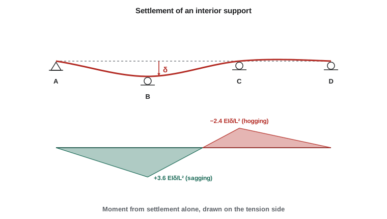
The office wing corridor beam of lesson 2 bears on a footing at B that the geotechnical report says may settle more than the others. The question is what a differential settlement does to the beam's moments.
Worked problem
Settlement of an interior support
The three-span corridor beam of lesson 2 has spans of 6.0 m and \(EI = 30\,000\ \text{kN·m}^2\). Support B settles 10 mm relative to A, C and D. Find the reactions and support moments caused by the settlement alone, then combine them with the factored uniform load of 15.0 kN/m.
Show solution
- Redundants as before: \(X_1 = R_B\), \(X_2 = R_C\), upward. The flexibility matrix from lesson 2 is
- \[\mathbf{F} = \frac{L^3}{EI}\begin{bmatrix} 4/9 & 7/18 \\ 7/18 & 4/9 \end{bmatrix}\]
- With no load, \(\Delta_{10} = \Delta_{20} = 0\). The prescribed displacements are \(\Delta_1 = -\delta\) at B and \(\Delta_2 = 0\) at C.
- Solving \(\mathbf{F}\mathbf{X} = [-\delta,\ 0]^T\) (the determinant of the bracketed matrix is 15/324):
- \[X_1 = -9.6\,\frac{EI\delta}{L^3} \qquad X_2 = +8.4\,\frac{EI\delta}{L^3}\]
- \[\frac{EI\delta}{L^3} = \frac{30\,000(0.010)}{6.0^3} = 1.389\ \text{kN} \quad\to\quad R_B = -13.33\ \text{kN},\ R_C = +11.67\ \text{kN}\]
- End reactions by moments about D and vertical equilibrium: \(R_A = 5.00\) kN, \(R_D = -3.33\) kN. Support moments: \(M_B = R_A L = +30.0\ \text{kN·m}\), \(M_C = R_D L = -20.0\ \text{kN·m}\), that is \(3.6\,EI\delta/L^2\) and \(-2.4\,EI\delta/L^2\).
- Combined with the load case (\(M_B = M_C = -54.0\) kN·m): \(M_B = -24.0\ \text{kN·m}\), \(M_C = -74.0\ \text{kN·m}\).
Answer: A 10 mm settlement at B relieves the hogging moment over B but raises the moment over C by 37 per cent, from 54.0 to 74.0 kN·m, and increases the reaction at C from 99.0 to 110.7 kN. The beam sheds load away from the settling support toward its neighbours. If the settlement could equally occur at C, the design must cover both cases.
Look at the form of the result: moment proportional to \(EI\delta/L^2\). Short, stiff spans are much more sensitive to settlement than long, flexible ones. Halving the span multiplies the settlement moment by four for the same \(\delta\). This is why short-span continuous concrete structures on variable ground often need careful foundation design, while long-span steel beams tolerate the same settlement easily.
Elastic supports
Sometimes the settlement is not known in advance but depends on the reaction: a beam bearing on a soil-supported footing, a column that shortens under load, or a beam supported by another flexible beam. Model such a support as a spring of stiffness k, so that its displacement is \(-X_i/k\) (downward when the reaction is upward). Moving this term to the left-hand side of the compatibility equation simply adds \(1/k\) to the diagonal term:
A rigid support has \(1/k = 0\); a support so soft that \(1/k\) dominates attracts almost no reaction, and the beam behaves as if that support were absent. The same device models a girder supported on a flexible transfer beam.
Temperature
Temperature effects come in two forms. A uniform change \(\Delta T\) lengthens a member by \(\alpha\,\Delta T\,L\), where \(\alpha\) is the coefficient of thermal expansion (about \(12 \times 10^{-6}\) per degree Celsius, or \(6.5 \times 10^{-6}\) per degree Fahrenheit, for both steel and concrete). A temperature difference between the top and bottom faces bends the member into a uniform curvature
where d is the depth. A sun-heated roof or deck is hotter on top, so it tends to hog upward. In the primary structure these strains produce displacements, found by virtual work with the thermal strain in place of the elastic one:
For the corridor beam with a sun-heated top, the uniform curvature lifts the primary beam off supports B and C, the compatibility equations pull it back down, and the result is a sagging moment over the interior supports of \(1.2\,EI\kappa_T\). For comparison, a two-span beam develops \(1.5\,EI\kappa_T\) over its middle support, and a beam fixed at both ends develops a uniform \(EI\kappa_T\) along its whole length with no reactions at all.
For the corridor beam with the top 15 °C hotter than the bottom and \(d = 0.40\) m, \(\kappa_T = 12 \times 10^{-6}(15)/0.40 = 4.5 \times 10^{-4}\) per metre, and the moment over B and C is \(1.2(30\,000)(4.5 \times 10^{-4}) = 16.2\ \text{kN·m}\), sagging. That offsets part of the 54.0 kN·m hogging from load, but a cold-top case of the opposite sign adds to it.
Uniform temperature in a frame behaves similarly. If the garage portal frame of lesson 3 is erected in winter and the roof beam warms by \(\Delta T\), the beam tries to push the bases apart by \(\alpha\,\Delta T\,L\). The compatibility equation gives \(H = \alpha\,\Delta T\,L/f_{11}\). For a single-bay portal with flexible columns the resulting thrust is small because tall columns bend easily. In a long building, however, the movements accumulate along the length, and frames near the ends of a long braced wall can be strained heavily. Expansion joints break long buildings into lengths that can move freely, which removes the redundancy that causes the forces.
Lack of fit
Steel members are fabricated to tolerances, and a redundant member that is slightly too long or too short must be forced into place. The fabrication error acts exactly like a temperature change in that member: it is an initial strain. If a redundant truss member is made too short by e, the gap at the cut in the primary structure is e, and the compatibility equation becomes \(f_{11}X = e\) for a single redundant.
Worked problem
A short diagonal in the X-braced bay
Diagonal 1–3 of the X-braced bay in lesson 3 is fabricated 3.0 mm too short. All members have \(A = 1000\ \text{mm}^2\) and \(E = 200\ \text{GPa}\). Find the member forces when the bay is assembled with no wind load.
Show solution
- From lesson 3, \(AE\,f_{11} = \sum n^2 L = 25.92\) m, and \(AE = 1000(200\,000)/1000 = 200\,000\ \text{kN}\).
- The member is short, so it must be stretched to fit: it ends up in tension.
- \[X = \frac{e\,AE}{\sum n^2 L} = \frac{0.0030(200\,000)}{25.92} = 23.1\ \text{kN}\]
- Other members: \(N = X\,n\), so both diagonals 23.1 kN tension, chords \(-0.8(23.1) = -18.5\) kN and columns \(-0.6(23.1) = -13.9\) kN.
Answer: A 3 mm error locks in a 23 kN force in both diagonals, about 60 per cent of the wind force they were designed for. This is why bracing is detailed with slotted holes or adjustable ends, and why rod bracing is often deliberately pretensioned with turnbuckles: a controlled lack of fit keeps the rods taut so that both act under small loads.
Self-straining effects in design
The NBC treats these effects as the load T: the effects of temperature change, shrinkage, moisture change, creep and differential settlement. T appears in the load combinations with its own companion factors, and Part 4 also expects the designer to consider these movements where they are significant. Concrete shrinkage, which shortens members over months, is handled like a uniform temperature drop of the same strain.
| Effect | Enters the force method as | Scales with |
|---|---|---|
| Support settlement | Prescribed \(\Delta_i\) on the right-hand side | \(EI\delta/L^2\) for moment |
| Elastic support | \(1/k\) added to \(f_{ii}\) | Ratio of support to member stiffness |
| Uniform temperature | \(\sum \int n_i\,\alpha\Delta T\,dx\) in \(\Delta_{i0}\) | \(AE\,\alpha\Delta T\) for axial force |
| Temperature gradient | \(\sum \int m_i\,\kappa_T\,dx\) in \(\Delta_{i0}\) | \(EI\kappa_T\) for moment |
| Lack of fit e | Gap e in \(\Delta_{i0}\) at the cut | \(AE\,e/L\) for axial force |
Solving it in code
Sofia extended her three-span program so that each case can include loads, support settlements and a thermal curvature. The flexibility matrix is computed once and reused, exactly as the theory suggests. The last line superposes load and settlement; check that its moments are the sums of the first two lines.
# Force method with settlement and a temperature gradient: three-span beam A-B-C-D
# Redundants: reactions at B and C. Compatibility F X = Delta - Delta0.
L = [6.0, 6.0, 6.0]                # spans (m)
EI = 30000.0                       # flexural stiffness (kN*m^2)
Lt = sum(L); xB = L[0]; xC = L[0] + L[1]; starts = [0.0, L[0], xC]

def M0_load(w):                    # primary simple beam A-D, uniform load w[i] on span i
    RA = sum(wi * Li * (Lt - (s + Li / 2)) for wi, Li, s in zip(w, L, starts)) / Lt
    def M(x):
        m = RA * x
        for wi, Li, s in zip(w, L, starts):
            if x > s:
                a = min(x, s + Li) - s
                m -= wi * a * (x - (s + a / 2))
        return m
    return M

def m_unit(xp):                    # unit upward force at xp on the primary beam
    return lambda x: -(Lt - xp) / Lt * x + (x - xp if x > xp else 0.0)

n = 6000; h = Lt / n; xs = [i * h for i in range(n + 1)]
def integ(g):
    return sum((g(xs[i]) + g(xs[i + 1])) / 2 * h for i in range(n))

mB, mC = m_unit(xB), m_unit(xC)
F = [[integ(lambda x: mB(x) ** 2) / EI, integ(lambda x: mB(x) * mC(x)) / EI],
     [integ(lambda x: mC(x) * mB(x)) / EI, integ(lambda x: mC(x) ** 2) / EI]]

def solve2(F, r):
    det = F[0][0] * F[1][1] - F[0][1] * F[1][0]
    return [(r[0] * F[1][1] - r[1] * F[0][1]) / det, (r[1] * F[0][0] - r[0] * F[1][0]) / det]

def case(name, w=(0.0, 0.0, 0.0), settle=(0.0, 0.0), kappa=0.0):
    M0 = M0_load(list(w))
    # primary displacements at B and C (upward positive): load term plus thermal curvature term
    D0 = [integ(lambda x: mB(x) * (M0(x) / EI + kappa)), integ(lambda x: mC(x) * (M0(x) / EI + kappa))]
    RB, RC = solve2(F, [settle[0] - D0[0], settle[1] - D0[1]])
    W = sum(wi * Li for wi, Li in zip(w, L))
    RA = (sum(wi * Li * (Lt - (s + Li / 2)) for wi, Li, s in zip(w, L, starts)) - RB * (Lt - xB) - RC * (Lt - xC)) / Lt
    RD = W - RA - RB - RC
    MB = RA * xB - w[0] * xB ** 2 / 2
    MC = RD * L[2] - w[2] * L[2] ** 2 / 2
    print("%-22s RA %6.2f  RB %7.2f  RC %7.2f  RD %6.2f kN   MB %7.2f  MC %7.2f kN*m"
          % (name, RA, RB, RC, RD, MB, MC))

kappa_sun = -12e-6 * 15.0 / 0.40   # top 15 C hotter than bottom, depth 0.40 m (hogging curvature)
case("load 15 kN/m", w=(15.0, 15.0, 15.0))
case("B settles 10 mm", settle=(-0.010, 0.0))
case("sun gradient", kappa=kappa_sun)
case("load + settlement", w=(15.0, 15.0, 15.0), settle=(-0.010, 0.0))load 15 kN/m RA 36.00 RB 99.00 RC 99.00 RD 36.00 kN MB -54.00 MC -54.00 kN*m B settles 10 mm RA 5.00 RB -13.33 RC 11.67 RD -3.33 kN MB 30.00 MC -20.00 kN*m sun gradient RA 2.70 RB -2.70 RC -2.70 RD 2.70 kN MB 16.20 MC 16.20 kN*m load + settlement RA 41.00 RB 85.67 RC 110.67 RD 32.67 kN MB -24.00 MC -74.00 kN*m
Try moving the settlement to C, or applying it at both B and C equally. Equal settlement of B and C relative to the ends produces symmetric moments; equal settlement of all four supports produces no forces at all, since it is a rigid-body movement. Only differential settlement matters.
Common mistakes
MistakeGetting the sign of a settlement wrong in the compatibility equation.
InsteadMeasure the settlement in the positive direction of the redundant; a downward settlement is negative for an upward reaction.
MistakeRecomputing the flexibility matrix for each new settlement or temperature case.
InsteadOnly the right-hand side changes; reuse F.
MistakeAssuming a stiffer member will reduce settlement or thermal stress.
InsteadSelf-straining forces are proportional to stiffness; a stiffer member attracts more force.
MistakeIncluding uniform settlement of all supports.
InsteadOnly differential settlement produces forces; a uniform movement is a rigid-body displacement.
Summary and key terms
- Settlements enter as prescribed \(\Delta_i\); temperature and misfit add to \(\Delta_{i0}\); F is unchanged.
- Settlement moments scale with \(EI\delta/L^2\): short, stiff spans are most sensitive.
- An elastic support adds \(1/k\) to the diagonal flexibility term.
- Thermal curvature \(\kappa_T = \alpha\Delta T/d\); a fixed-ended beam develops \(EI\kappa_T\).
- Lack of fit acts as an initial strain; for a single redundant \(X = e/f_{11}\).
- Self-straining effect
- A force caused by restrained deformation rather than by applied load.
- Differential settlement
- A difference in vertical movement between supports of the same structure.
- Elastic support
- A support whose displacement is proportional to its reaction.
- Thermal gradient
- A temperature difference through the depth of a member.
- Coefficient of thermal expansion
- The strain per degree of temperature change.
- Lack of fit
- A difference between the fabricated and the required length of a member.
- Expansion joint
- A deliberate break in a structure that lets parts move independently.
Practice problems
Work each problem on paper first, then reveal the answer to check.
A fixed-fixed beam with \(EI = 40\,000\ \text{kN·m}^2\) and depth 0.50 m has its top 20 °C hotter than its bottom. Find the moment.
Show answer
\(\kappa_T = 12 \times 10^{-6}(20)/0.50 = 4.8 \times 10^{-4}\) per metre; \(M = EI\kappa_T = 19.2\ \text{kN·m}\), uniform.
In the settlement example, what moment over C would a 20 mm settlement at B produce on its own?
Show answer
Twice the 10 mm value: \(-40.0\ \text{kN·m}\), since the response is linear.
Why does an elastic support add \(1/k\) to \(f_{ii}\)?
Show answer
Its displacement \(-X_i/k\) depends on the redundant, so moving it to the left side of the compatibility equation adds \(1/k\) to the coefficient of \(X_i\).
Does a uniform temperature change cause forces in a simply supported beam on a pin and roller?
Show answer
No; the roller lets the beam expand freely and the structure is determinate.
What does deliberately shortening a bracing rod achieve?
Show answer
It pretensions the rod so that it stays taut and both diagonals act under small loads.
Why are long buildings divided by expansion joints?
Show answer
Each length can then expand and contract freely, removing the restraint that would cause thermal forces.
Lesson quiz · 5 questions
Score 60% or more to complete this lesson.
Create a free account to save your progress, take quizzes and earn a certificate.