
CIV-321 · Lesson 12 of 12 · 22 min
Modelling with structural software and checking results
Every method in this course is now inside the analysis program on an engineer's desk. The program assembles and solves stiffness matrices with thousands of degrees of freedom in seconds, but it does exactly what the model tells it, including the mistakes. The engineer's job has shifted from solving equations to building models that represent the structure faithfully, combining load cases correctly, and proving that the output is right. This lesson walks through those three tasks for the operations centre, using the hand methods of lessons 2 to 11 as the checks.
From structure to model
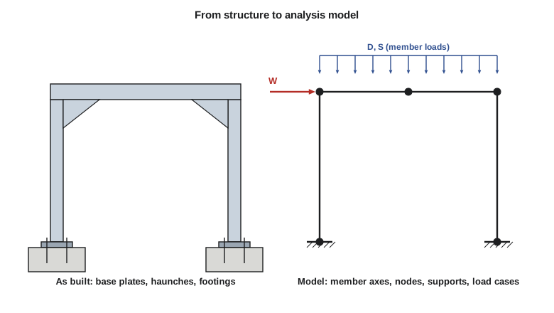
A model represents each member by its centreline and each connection by a node, and it replaces the real supports, connections and loads by idealized ones. CIV-224 lesson 1 introduced these idealizations; in an indeterminate structure they matter more, because the force distribution depends on relative stiffness and on boundary conditions. The main decisions are these.
- Supports. Is the column base pinned, fixed or something in between? A base plate with four anchor rods on a footing that can rotate is closer to a pin than to a fixed support. Lesson 6 showed that the choice changes the sway of the garage frame by a factor of more than four. If in doubt, analyse both bounds, or model the base as a rotational spring.
- Connections. Simple shear connections are modelled with moment releases; moment connections as rigid. A beam that is released at both ends in a model but welded in reality will crack the connection or the slab at its ends, so the detail and the model must agree.
- Member properties. Use gross section properties for steel. For concrete, design standards specify reduced effective stiffnesses for cracked members (beams are typically given a smaller fraction of their gross moment of inertia than columns), and these change the distribution of moments in an indeterminate frame.
- Rigid zones and offsets. Where deep members meet, the joint region is much stiffer than the members, and centreline models overestimate flexibility. Programs allow rigid end offsets for this.
- Diaphragms. A concrete floor slab is very stiff in its own plane and is often modelled as a rigid diaphragm that ties all the nodes of a floor together horizontally, just as the inextensible beam tied the garage corners together.
- Load application. Gravity loads on beams are entered as member loads; wind is applied as nodal forces or as pressures on wall elements; temperature and settlement as imposed strains and support displacements (lesson 4).
Load cases, combinations and envelopes
A model is analysed once for each load case: dead, live, snow, wind in each direction, temperature, and so on, each with its specified (unfactored) values. Because the analysis is linear, the results for any load combination are the factored sums of the case results. This is far more efficient than analysing each combination separately, and it lets the program form an envelope: the most positive and most negative value of every response over every combination.
CIV-224 lesson 2 set out the NBC load combinations. In the strength cases, a principal load is taken with its full factor and companion loads with reduced factors: case 1 is \(1.4D\); case 2 is \(1.25D + 1.5L\) with companion \(1.0S\) or \(0.4W\); case 3 is \(1.25D + 1.5S\) with companion \(1.0L\) or \(0.4W\); case 4 is \(1.25D + 1.4W\) with companion \(0.5L\) or \(0.5S\); case 5 covers earthquake. Where dead load counteracts the effect being checked, as for uplift or overturning, its factor drops to 0.9.
Two points are easy to miss. First, each load that can act in more than one direction (wind from the left or the right, live load on any pattern of spans) multiplies the number of combinations, and the envelope must include all of them. Second, the combination that governs is different at different points: the roof load case controls the corners of the garage frame, but the reduced dead load with full wind controls the reversal of moment at the windward base.
Worked problem
Combining cases for the garage frame
For one garage end frame, the specified roof loads are \(D = 3.0\) kN/m and \(S = 5.0\) kN/m, and the specified wind is \(W = 20.0\) kN at roof level. From one analysis per case (lessons 6 and 11), a roof load of 1 kN/m gives \(-20.25\) kN·m at each corner and \(+10.125\) kN·m at each base, and 1 kN of wind to the right gives \(+1.2\) at B, \(-1.2\) at C, \(-1.8\) at A and \(+1.8\) kN·m at D (negative means tension on the outside face). Find the governing corner and base moments.
Show solution
- Snow as principal load, wind to the right: roof load \(1.25(3.0) + 1.5(5.0) = 11.25\) kN/m.
- \[M_C = 11.25(-20.25) + 0.4(20.0)(-1.2) = -227.8 - 9.6 = -237.4\ \text{kN·m}\]
- \[M_D = 11.25(10.125) + 0.4(20.0)(1.8) = 113.9 + 14.4 = 128.3\ \text{kN·m}\]
- Wind as principal load with \(0.9D\) and no snow: roof load 2.7 kN/m.
- \[M_A = 2.7(10.125) + 1.4(20.0)(-1.8) = 27.3 - 50.4 = -23.1\ \text{kN·m}\]
Answer: The corners are governed by case 3, \(1.25D + 1.5S + 0.4W\), at 237.4 kN·m, and so are the bases at 128.3 kN·m. The windward base reverses sign under \(0.9D + 1.4W\), with 23.1 kN·m of tension on its outside face, so the base plate and anchor rods must be designed for moment in both directions. A design based on the snow case alone would miss this.
For frames whose sway is significant, the linear superposition used here is only the first step. Second-order effects depend on the total gravity load in each combination, so a second-order analysis must be run combination by combination rather than case by case, or the sway moments amplified for each combination. Both design standards set out when this is required.
Checking the output
An analysis program never reports that it was given the wrong model. Every result that will be used in design should pass a set of checks, and the hand methods of this course provide them.
| Check | How | Catches |
|---|---|---|
| Statics | Sum the reactions in each direction for each load case and compare with the applied loads | Loads entered twice, missing loads, wrong units or directions |
| Deflected shape | Plot it for each case; does it look physically sensible? | Missing supports, wrong releases, disconnected members |
| Symmetry | Symmetric structures under symmetric load give symmetric results | Input typing errors in one half |
| Hand estimates | Coefficients such as \(wL^2/10\) and \(wL^2/12\), the portal method, simple frame formulas | Wrong stiffnesses, wrong boundary conditions |
| Magnitude of deflection | Compare with span/360 or drift limits; implausibly large or small values point to errors | Wrong units of E or I, missing moment connections |
| Stability messages | Never ignore warnings of singular or ill-conditioned matrices | Mechanisms, missing restraints, members connected only at pins |
| Sensitivity | Change an uncertain assumption (base fixity, cracked stiffness) and see how much results move | Design that depends on a fragile assumption |
For the garage frame, statics gives the clearest check. Under case 3 the roof carries \(11.25(18.0) = 202.5\) kN, so the two vertical base reactions must total 202.5 kN; under any wind case the horizontal base reactions must total the factored wind. The symmetric snow case must give equal corner moments. The corner moment under the full uniform load must equal \(wL^2/16\) for this frame (lesson 6), or, for a beam of different relative stiffness, a value between the fixed-end moment \(wL^2/12\) and zero.
The office wing comparison in lesson 11 showed that an approximate method can be wrong by a third for some members. That does not mean the check is useless; it means the engineer must understand why the two differ. When a model and a hand check disagree, one of them is wrong or they represent different structures, and finding out which is the most valuable hour of the analysis.
Common modelling errors
Experience across many projects shows the same errors recurring. Units are the classic one: a modulus entered in megapascals where the program expects kilopascals, or kips per square inch where it expects kips per square foot, makes every displacement wrong by a factor of a thousand or 144 while leaving the forces of a determinate structure unchanged, so a statics check alone cannot catch it. Local axis orientation is another: a member with its strong axis rotated 90 degrees has a fraction of its intended stiffness and attracts little moment. Releases are a third: releasing both ends of every beam in a frame meant to be rigid turns it into a mechanism under lateral load, which a good program reports as instability; releasing too few makes the frame stiffer than built. Finally, load patterns: a model that has only all-spans-loaded live load misses the pattern effects of lesson 2.
Sharing the work
Kestrel Bay's practice is that every model has an independent check before its results are used. Priya reviews the model input line by line against the drawings, Owen prepares hand checks of key members using the methods of this course, and Sofia's small programs, like those in these lessons, give a second, transparent calculation for the critical frames. The model, the checks and the reasons for any differences are kept together in the calculation package, so that anyone reviewing the design later can follow the reasoning. A design is only as reliable as the least-checked assumption in it.
Solving it in code
The program forms every combination from the unit-case results, with wind in both directions, and builds the envelope at the four critical sections. It ends with a statics check on the unit wind case.
# Load combinations and envelope for the garage end frame (NBC strength combinations)
# Unit-case results come from one linear analysis per load case (the lesson 11 program).
# Sign: negative = tension on the outside face of the frame.
h = 6.0                              # column height (m)
unit = [  # location, moment per kN/m of roof load, moment per kN of wind to the right (kN*m)
    ("corner B", -20.25, +1.2),
    ("corner C", -20.25, -1.2),
    ("base A", +10.125, -1.8),
    ("base D", +10.125, +1.8),
]
D, S, W = 3.0, 5.0, 20.0             # specified dead (kN/m), snow (kN/m), wind (kN) on one frame
combos = [  # case, factor on D, factor on S, factor on W (wind can act either way)
    ("1  1.4D", 1.4, 0.0, 0.0),
    ("2  1.25D + 0.4W", 1.25, 0.0, 0.4),
    ("3  1.25D + 1.5S + 0.4W", 1.25, 1.5, 0.4),
    ("4  1.25D + 1.4W + 0.5S", 1.25, 0.5, 1.4),
    ("4  0.9D + 1.4W", 0.9, 0.0, 1.4),
]
print("%-34s" % "combination" + "".join("%10s" % u[0] for u in unit))
env_max = [-1e9] * len(unit); env_min = [1e9] * len(unit)
for name, fd, fs, fw in combos:
    for sign in ((1, -1) if fw else (1,)):
        roof = fd * D + fs * S
        vals = [roof * gm + sign * fw * W * wm for _, gm, wm in unit]
        env_max = [max(a, b) for a, b in zip(env_max, vals)]
        env_min = [min(a, b) for a, b in zip(env_min, vals)]
        label = name + ((", W right" if sign > 0 else ", W left") if fw else "")
        print("%-34s" % label + "".join("%10.1f" % v for v in vals))
print("%-34s" % "envelope, most positive" + "".join("%10.1f" % v for v in env_max))
print("%-34s" % "envelope, most negative" + "".join("%10.1f" % v for v in env_min))
# check the unit wind case: the two column shears must add up to the 1 kN applied
shear = (abs(unit[0][2]) + abs(unit[2][2])) / h + (abs(unit[1][2]) + abs(unit[3][2])) / h
print("check: column shears under 1 kN of wind add to %.2f kN" % shear)combination corner B corner C base A base D 1 1.4D -85.0 -85.0 42.5 42.5 2 1.25D + 0.4W, W right -66.3 -85.5 23.6 52.4 2 1.25D + 0.4W, W left -85.5 -66.3 52.4 23.6 3 1.25D + 1.5S + 0.4W, W right -218.2 -237.4 99.5 128.3 3 1.25D + 1.5S + 0.4W, W left -237.4 -218.2 128.3 99.5 4 1.25D + 1.4W + 0.5S, W right -93.0 -160.2 12.9 113.7 4 1.25D + 1.4W + 0.5S, W left -160.2 -93.0 113.7 12.9 4 0.9D + 1.4W, W right -21.1 -88.3 -23.1 77.7 4 0.9D + 1.4W, W left -88.3 -21.1 77.7 -23.1 envelope, most positive -21.1 -21.1 128.3 128.3 envelope, most negative -237.4 -237.4 -23.1 -23.1 check: column shears under 1 kN of wind add to 1.00 kN
Each row is a factored sum, so adding a load case (a roof live load, a crane load, a temperature case) is a matter of one more column in the unit table and one more factor in each combination. That is precisely how analysis programs organize their combinations, and why understanding superposition matters even when the computer does the arithmetic.
Common mistakes
MistakeAnalysing only the factored combination expected to govern.
InsteadAnalyse each load case once and combine, so every combination and both wind directions are covered.
MistakeAccepting results that fail a statics check because they look reasonable.
InsteadReactions must balance loads exactly; find the cause before using any result.
MistakeChoosing fixed bases in the model because they reduce drift, with pinned details on the drawings.
InsteadModel the supports that will be built, or detail the bases to provide the fixity assumed.
MistakeSuperposing second-order results from separate load cases.
InsteadRun second-order analysis for each combination, because the effect depends on the total load.
Summary and key terms
- A model idealizes supports, connections, properties and loads; in indeterminate structures these choices change the forces.
- Analyse each load case once and combine linearly; envelopes give the extreme values over all combinations.
- Different combinations govern at different points; reduced dead load with full wind often governs reversals.
- Check every model: statics, deflected shape, symmetry, hand estimates, magnitudes and warnings.
- Second-order effects must be handled combination by combination.
- Analysis model
- An idealized representation of a structure by nodes, elements, supports and loads.
- Load case
- One source of load with its specified or nominal values, analysed separately.
- Load combination
- A factored sum of load cases defined by the design standard.
- Envelope
- The maximum and minimum of each response over all load combinations.
- Rigid diaphragm
- A floor or roof modelled as infinitely stiff in its own plane.
- Rigid end offset
- A stiff length at the end of a member representing the joint region.
- Independent check
- A separate calculation, by another person or method, that confirms key results.
Practice problems
Work each problem on paper first, then reveal the answer to check.
Why can load cases be analysed separately and combined afterwards?
Show answer
Because the analysis is linear: responses are proportional to loads and can be superposed.
In the garage example, what is the corner moment under case 1, \(1.4D\)?
Show answer
\(1.4(3.0)(-20.25) = -85.0\ \text{kN·m}\).
Which check would detect a modulus entered in the wrong units for a determinate structure?
Show answer
The deflection magnitude check; the forces in a determinate structure do not depend on E.
Why does the windward base moment reverse under the reduced dead load combination?
Show answer
Gravity load produces positive base moment, wind produces negative moment at the windward base, and with only 0.9D the wind effect dominates.
Name two ways to model a base that is neither pinned nor fixed.
Show answer
A rotational spring at the base, or analysing both pinned and fixed bounds and designing for the worse.
What should an engineer do when a model and a hand check differ substantially?
Show answer
Find the reason before using either: an input error, a different assumption, or a genuine limit of the approximate method.
Lesson quiz · 5 questions
Score 60% or more to complete this lesson.
Create a free account to save your progress, take quizzes and earn a certificate.