
CIV-250 · Lesson 6 of 12 · 24 min
Angles, bearings, azimuths and total stations
Distances alone cannot fix positions on a plane; directions are needed too. Surveyors measure horizontal angles between lines, and from a known starting direction they compute the direction of every other line. Combined with distances, those directions give coordinates. This lesson covers how angles and directions are expressed, how azimuths and bearings are computed and converted, the reference meridians that directions are measured from, and the total station, the instrument that measures angles and distances together in almost every survey today.
Leah's assignment this week is to work with Grant on the Coulee Ridge control traverse. Before she can compute it, she needs to be comfortable with angle arithmetic in degrees, minutes and seconds, the difference between an azimuth and a bearing, and the field procedure that cancels the instrument's own small errors.
Units of angle
Surveyors in North America measure angles in sexagesimal units: 360 degrees in a circle, 60 minutes in a degree and 60 seconds in a minute, written as 47°18′24″. Calculators and programs work in decimal degrees or radians, so conversions are routine: 47°18′24″ equals \(47 + 18/60 + 24/3600 = 47.30667°\). One second of arc is a very small angle, about 4.85 millionths of a radian. A useful rule is that one second subtends about 5 mm at 1 km, so an angular error of 5″ at 500 m moves a point sideways by about 12 mm.
Some countries use gons, also called grads, with 400 gon in a circle. They appear on some instrument menus and in European software, so it is worth checking the angle units set on any instrument or program before starting work.
Kinds of horizontal angles
A horizontal angle is the angle between two lines projected onto a horizontal plane. The most common forms in surveying are:
- Angles to the right: measured clockwise from the backsight line to the foresight line, from 0° to 360°. Most total stations measure angles right by default, and traverse computations use them directly.
- Interior angles: the angles inside a closed polygon. For a polygon of \(n\) sides, they must sum to \((n - 2) \times 180°\), which provides the angular check on a closed traverse (lesson 7).
- Deflection angles: the angle between the extension of the previous line and the next line, recorded as right (R) or left (L), from 0° to 180°. Deflection angles are common on route surveys, such as highways and pipelines, and for laying out curves (lesson 12).
Reference meridians
Directions are measured from a reference line called a meridian. Which meridian is used must always be stated.
- True or geodetic north: the direction toward the North Pole along a meridian of longitude. Geodetic meridians converge toward the pole, so true north at the east side of a large site points in a slightly different direction from true north at the west side.
- Grid north: the direction of the north axis of a map projection. On a projection, all grid north lines are parallel, which makes computations simple. Grid north differs from true north by the convergence angle, which depends on location relative to the projection's central meridian (lesson 9).
- Magnetic north: the direction a compass needle points. The angle between true north and magnetic north, called magnetic declination, varies with place and slowly over time. In southern Alberta it is roughly 10° east in the mid-2020s and decreasing, but the current value should always be taken from Natural Resources Canada's magnetic field calculator. Magnetic bearings appear on many old plans and are still useful for rough orientation, but never for precise work.
- Assumed north: an arbitrary direction chosen for a small, isolated survey. Assumed bearings must be clearly labelled, because a later surveyor trying to relate the survey to anything else will need to know.
Azimuths and bearings
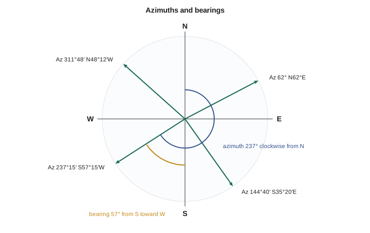
Directions of lines are expressed as azimuths or bearings. An azimuth is measured clockwise from north, from 0° to 360°. A bearing is the acute angle, from 0° to 90°, between the line and the north or south end of the meridian, with a letter showing which side, east or west. A line with an azimuth of 237°14′30″ has a bearing of S57°14′30″W. Azimuths are easier for computation, while bearings are traditional on legal plans and descriptions.
| Quadrant | Azimuth range | Bearing from azimuth | Azimuth from bearing |
|---|---|---|---|
| NE | 0° to 90° | N \(Az\) E | \(Az = \beta\) |
| SE | 90° to 180° | S \((180° - Az)\) E | \(Az = 180° - \beta\) |
| SW | 180° to 270° | S \((Az - 180°)\) W | \(Az = 180° + \beta\) |
| NW | 270° to 360° | N \((360° - Az)\) W | \(Az = 360° - \beta\) |
Every line has two directions. The back azimuth, the direction of the same line traveled the other way, differs by 180°: if the azimuth from A to B is 62°18′40″, the azimuth from B to A is 242°18′40″. For bearings, the back bearing has the same angle with both letters reversed: N62°18′40″E becomes S62°18′40″W. Strictly, on a geodetic meridian the back azimuth also differs by the convergence of meridians between the two ends, which is why grid azimuths are used for computation.
Computing azimuths along a traverse
Given the azimuth of one line and the angle measured to the right at each station, the azimuth of each following line is the back azimuth of the previous line plus the angle right. If the result exceeds 360°, subtract 360°.
Worked problem
Propagating azimuths
The grid azimuth of line CR-1 to CR-2 is 62°18′40″. At CR-2, the angle right from CR-1 to CR-3 is 196°25′10″. At CR-3, the angle right from CR-2 to CR-4 is 88°51′35″. Find the azimuths of CR-2 to CR-3 and CR-3 to CR-4, and give each as a bearing.
Show solution
- Back azimuth of CR-1 to CR-2: \(62°18'40'' + 180° = 242°18'40''\).
- \[Az_{2\to3} = 242°18'40'' + 196°25'10'' = 438°43'50'' - 360° = 78°43'50''\]
- As a bearing this is N78°43′50″E.
- Back azimuth of CR-2 to CR-3: \(78°43'50'' + 180° = 258°43'50''\).
- \[Az_{3\to4} = 258°43'50'' + 88°51'35'' = 347°35'25''\]
- As a bearing this is \(360° - 347°35'25'' = \) N12°24′35″W.
Answer: CR-2 to CR-3 has azimuth 78°43′50″ (N78°43′50″E) and CR-3 to CR-4 has azimuth 347°35′25″ (N12°24′35″W). A quick sketch confirms the directions: after a slight turn to the right at CR-2, the line runs nearly east, then turns sharply left at CR-3 toward the north-northwest.
# Angle arithmetic, azimuth propagation and bearing conversion
def dms(d, m=0, s=0):
    return d + m / 60 + s / 3600

def to_dms(x):
    x = x % 360
    d = int(x); m = int((x - d) * 60); s = round(((x - d) * 60 - m) * 60, 1)
    if s >= 60: s -= 60; m += 1
    if m >= 60: m -= 60; d += 1
    return f"{d}°{m:02d}'{s:04.1f}\""

def bearing(az):
    az %= 360
    if az <= 90:  return f"N{to_dms(az)}E"
    if az <= 180: return f"S{to_dms(180 - az)}E"
    if az <= 270: return f"S{to_dms(az - 180)}W"
    return f"N{to_dms(360 - az)}W"

az = dms(62, 18, 40)
angles_right = [("CR-2", dms(196, 25, 10)), ("CR-3", dms(88, 51, 35))]
names = ["CR-3", "CR-4"]
print(f"CR-1 to CR-2: {to_dms(az)}  {bearing(az)}")
for (stn, ang), nxt in zip(angles_right, names):
    az = (az + 180 + ang) % 360
    print(f"{stn} to {nxt}: {to_dms(az)}  {bearing(az)}")

# Face left / face right reduction
fl, fr = dms(47, 18, 20), dms(227, 18, 28)
mean = (fl + (fr - 180)) / 2
coll = ((fr - 180) - fl) / 2 * 3600
print(f"mean direction {to_dms(mean)}, half difference {coll:.1f} seconds")

# Lateral effect of an angular error
import math
for err, dist in ((5, 500), (1, 1000), (20, 100)):
print(f"{err}\" at {dist} m moves a point {dist * math.radians(err / 3600) * 1000:.1f} mm sideways")CR-1 to CR-2: 62°18'40.0" N62°18'40.0"E CR-2 to CR-3: 78°43'50.0" N78°43'50.0"E CR-3 to CR-4: 347°35'25.0" N12°24'35.0"W mean direction 47°18'24.0", half difference 4.0 seconds 5" at 500 m moves a point 12.1 mm sideways 1" at 1000 m moves a point 4.8 mm sideways 20" at 100 m moves a point 9.7 mm sideways
The total station
A total station combines an electronic theodolite, which measures horizontal and vertical angles with digital encoders, with an EDM and an onboard computer. The main parts are the tribrach, which attaches the instrument to the tripod and contains levelling screws and an optical or laser plummet for centring over a point; the alidade, the upper part that rotates about the vertical axis; the telescope, which rotates about the horizontal or trunnion axis; and the display and keyboard or a separate data collector. Robotic total stations add motors and automatic target recognition, so one person can operate the instrument remotely from the prism pole. Many instruments also scan, measuring thousands of reflectorless points per second.
Angular precision is specified as the standard deviation of a direction measured on both faces, typically 1″ to 5″ for survey instruments. A 5″ instrument is adequate for topography and most construction layout; control traverses and monitoring use 1″ or 2″ instruments.
Setting up and orienting
A setup begins by placing the tripod roughly over the point with its head level, attaching the instrument, and centring it with the plummet. The instrument is levelled with the circular bubble and then precisely with the electronic or plate level, and centring and levelling are repeated until both are right, since each adjustment disturbs the other. Centring errors matter most on short sights: a 2 mm centring error causes an angular error of about 40″ on a 10 m sight but only 0.8″ on a 500 m sight.
The instrument is then oriented. The operator sights a backsight point of known coordinates and enters its azimuth, or lets the data collector compute it from the coordinates of the occupied point and the backsight. From then on, every horizontal reading is an azimuth, and the data collector computes coordinates of every point observed. Good practice is to check the setup by measuring the distance and elevation to the backsight, or to a second known point, and comparing with the known values before collecting data.
Instrument errors and two-face observations
A theodolite's axes should satisfy several geometric conditions: the vertical axis truly vertical when the instrument is levelled, the line of sight perpendicular to the trunnion axis, the trunnion axis perpendicular to the vertical axis, and the vertical circle reading exactly 90° for a horizontal sight. Small departures from these conditions cause collimation error, trunnion axis error and vertical index error. Most of them change sign when the telescope is plunged, that is, rotated through 180° about the trunnion axis and the alidade turned through 180° so that the vertical circle is on the other side. A measurement taken on both faces, called face left and face right, or direct and reverse, and averaged, is free of these errors.
Worked problem
Reducing a two-face observation
A direction to CR-4 is read as 47°18′20″ on face left and 227°18′28″ on face right. Find the mean direction and the collimation effect.
Show solution
- Face right differs from face left by 180° plus twice the collimation effect. Subtract 180° from the face right reading: \(47°18'28''\).
- \[\text{mean} = \frac{47°18'20'' + 47°18'28''}{2} = 47°18'24''\]
- \[\text{half difference} = \frac{28'' - 20''}{2} = 4''\]
Answer: The mean direction is 47°18′24″, and the collimation effect is 4″. The mean is free of collimation error; if the half difference grows large or changes suddenly, the instrument should be checked and adjusted.
The vertical axis error, caused by imperfect levelling, does not cancel with two faces, so it is controlled by careful levelling and, in modern instruments, by a dual-axis compensator that measures the residual tilt and corrects the readings automatically.
Measuring angles precisely
For control work, each angle is measured several times. In the method of directions, the operator observes all the targets in turn on face left, then on face right in reverse order, which completes one set. Several sets are measured with the horizontal circle starting at different readings. The mean of the sets gives the best value, and the spread among them gives the precision. Specifications for control traverses often call for two to four sets and a maximum spread between sets of a few seconds.
Targets matter as much as instruments. A prism on a tripod with a tribrach, centred and levelled over the point, is far steadier than a prism held on a pole. For short sights, a pole that is tilted by just 1° moves a prism at 2 m height by 35 mm, which is a large angular error at 50 m. Many crews therefore use traverse kits, in which the instrument and targets share interchangeable tribrachs: after a set is measured, the instrument and target are swapped forward in their tribrachs without disturbing the centring, a technique called forced centring.
Safety and care
Total stations are precision instruments that are easily damaged. They should be carried in their case between setups, protected from rain and dust, allowed to adjust to the air temperature before precise work, and never left unattended on a tripod near traffic or in wind. Laser plummets and reflectorless EDM use laser light; operators must not point the beam at people's eyes and must follow the instrument's laser class precautions.
Common mistakes
MistakeAdding angles in degrees, minutes and seconds as if they were decimals.
InsteadConvert to decimal degrees, or carry minutes and seconds properly with 60 as the base.
MistakeForgetting to add 180° to get the back azimuth before adding the angle right.
InsteadThe next azimuth is the previous azimuth plus 180° plus the angle right, reduced to 0° to 360°.
MistakeMixing magnetic, true, grid and assumed directions on one plan.
InsteadState the reference meridian and convert all directions to it.
MistakeMeasuring control angles on one face only.
InsteadObserve on both faces and average to remove collimation, trunnion axis and index errors.
Summary and key terms
- Angles are measured in degrees, minutes and seconds; 1″ subtends about 5 mm at 1 km.
- Angles right, interior angles and deflection angles are the main kinds of horizontal angles.
- Directions are referred to true, grid, magnetic or assumed north, which must be stated.
- Azimuths run clockwise from north through 360°; bearings are acute angles from north or south; back directions differ by 180°.
- The azimuth of the next line is the previous azimuth plus 180° plus the angle right.
- A total station measures angles and distances; two-face observations cancel most instrument errors, but not poor levelling.
- Azimuth
- A direction measured clockwise from north, from 0° to 360°.
- Bearing
- A direction given as an acute angle east or west of north or south.
- Back azimuth
- The azimuth of a line in the opposite direction, differing by 180°.
- Angle right
- A horizontal angle measured clockwise from the backsight to the foresight.
- Deflection angle
- The angle between the extension of the previous line and the next line, right or left.
- Magnetic declination
- The angle between true north and magnetic north at a place and time.
- Face left and face right
- The two telescope positions used to observe angles so that instrument errors cancel.
- Forced centring
- Exchanging instruments and targets in fixed tribrachs so that centring is not disturbed.
Practice problems
Work each problem on paper first, then reveal the answer to check.
Convert azimuth 152°40′15″ to a bearing.
Show answer
S27°19′45″E.
Convert bearing N48°12′30″W to an azimuth.
Show answer
311°47′30″.
The azimuth of AB is 305°10′00″ and the angle right at B from A to C is 115°20′00″. Find the azimuth of BC.
Show answer
\(305°10' + 180° + 115°20' = 600°30' - 360° = 240°30'\).
How far sideways does a 10″ angular error move a point 300 m away?
Show answer
\(300 \times 10 \times 4.85 \times 10^{-6} = 0.015\) m.
Face left reads 112°05′42″ and face right reads 292°05′50″. Find the mean direction.
Show answer
112°05′46″.
Why does a 2 mm centring error matter more on short sights?
Show answer
The angular error equals the offset divided by the distance, so it is large when the distance is short.
Lesson quiz · 5 questions
Score 60% or more to complete this lesson.
Create a free account to save your progress, take quizzes and earn a certificate.