
AUTO-220 · Lesson 8 of 12 · 19 min
Charging systems and smart charging
Marcus Bell drives courier van 1 into Ridgeline at the end of his route with the battery warning lamp flickering on the dash. For a week, he says, the headlamps have pulsed slightly at idle, and on Tuesday the radio reset itself twice. Hal Osei wants the van back on the road tomorrow. Kiran's first instinct is to say "alternator," but Marty has trained her out of saying a part name before she has a measurement. "The alternator might be bad," he says. "Or a belt, or a wire, or the computer telling it to charge less on purpose. Modern charging systems are smarter than they used to be, and that makes them easier to misdiagnose."
This lesson explains how an alternator makes electricity, how its output is rectified and regulated, how the powertrain or body module now controls the charging voltage to save fuel and protect the battery, how electric vehicles charge their 12-volt battery without an alternator, and how to test a charging system and its belt drive.
How an alternator works
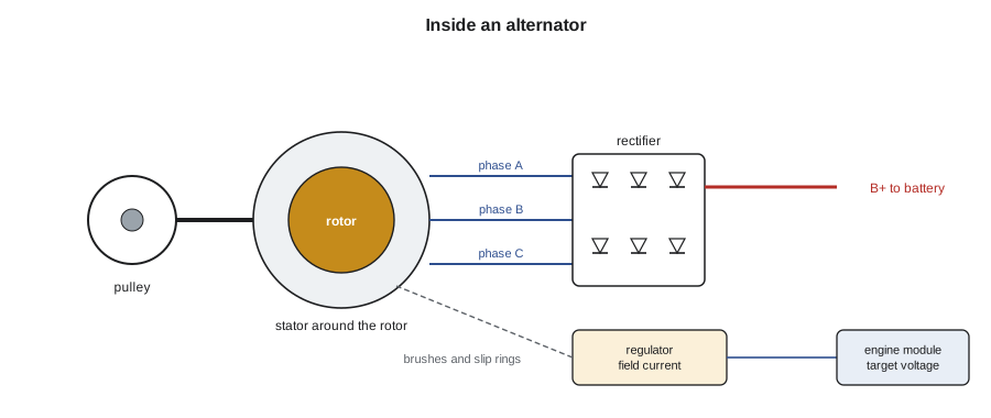
An alternator turns mechanical energy from the engine's drive belt into electrical energy. Inside, a rotor, a spinning electromagnet, turns inside a stationary set of windings called the stator. Current from the voltage regulator flows through brushes and slip rings into the rotor's field winding, making it a magnet with alternating north and south poles around its edge. As those poles sweep past the stator windings, they induce an alternating voltage in each of the stator's three windings. The amount of voltage depends on how fast the rotor spins and how strong its magnetic field is; the regulator controls the voltage by controlling the field current.
Because the stator produces three-phase alternating current, the alternator contains a rectifier: a bridge of six diodes, two for each phase, that let current pass in one direction only, turning the AC into DC at the output terminal. The output is not perfectly smooth; it has a small ripple left over from the rectified phases. If a diode fails, either open or shorted, the alternator loses part of its output and the ripple grows large, which can upset modules, make lamps pulse and drain the battery overnight through a leaking diode. Alternators are rated by their maximum output current, typically 120 to 250 amps for passenger vehicles and more for vans with extra electrical loads.
Regulation and smart charging
The regulator holds the system voltage within a target range by switching the rotor's field current on and off many times per second. On older vehicles, the regulator inside the alternator held a fixed target of about 14.2 to 14.6 volts, adjusted slightly for temperature. On most current vehicles, the engine control module or body control module sets the target, sending it to the regulator over a single control wire, as a pulse-width modulated signal, or over a LIN network link, and reading back how hard the alternator is working.
This is called smart charging, or regulated voltage control, and it has three main goals. It saves fuel: the alternator takes power from the engine, so the module charges less when the battery is full, sometimes letting the system fall to about 12.5 to 13 volts, and charges more during deceleration, when the energy would otherwise be wasted in braking. It protects the battery: using the battery monitoring sensor's readings of current, temperature and state of charge, the module charges a cold or discharged battery at a higher voltage, up to about 15 volts, and backs off as the battery fills. And it manages loads: when the battery is low or the alternator is at its limit, the module can reduce rear window defrosting, seat heating or idle stop-start to protect the starting ability. All of this means that a voltage reading that would have meant a fault 20 years ago may be perfectly normal today.
# Smart charging: the module chooses a target voltage from conditions (an illustrative strategy)
def target(soc, battery_c, decelerating, high_loads):
    v = 13.0 if soc >= 90 else 14.2 if soc >= 70 else 14.8
    if battery_c < 0: v += 0.3          # a cold battery accepts charge less readily
    if battery_c > 40: v -= 0.3
    if decelerating: v = max(v, 14.8)   # recover braking energy
    if high_loads and soc < 70: v = 14.8
    return min(v, 15.1)
cases = [("full battery, cruising", 95, 15, False, False), ("full battery, coasting downhill", 95, 15, True, False),
         ("after a cold start, 72 % charged", 72, -18, False, False), ("courier idle, 64 %, blower and lamps", 64, -5, False, True)]
for name, soc, temp, dec, loads in cases:
print(f"{name:<38} target {target(soc, temp, dec, loads):4.1f} V")full battery, cruising target 13.0 V full battery, coasting downhill target 14.8 V after a cold start, 72 % charged target 14.5 V courier idle, 64 %, blower and lamps target 14.8 V
Electric vehicles and hybrids
Electric vehicles and most hybrids have no conventional alternator. Their 12-volt system is supplied by a DC-to-DC converter that steps the high-voltage battery's 300 to 800 volts down to about 13 to 14.5 volts. The converter runs only when the vehicle is switched on or charging, and in some vehicles at intervals during long parking, which is why a weak 12-volt battery in an electric vehicle, as Dr. Singh found in the spring, causes problems mainly when the vehicle is first woken. Testing the converter's output is done from the 12-volt side with a meter and the scan tool; anything on the high-voltage side requires the training and equipment of AUTO-410.
Testing the charging system
Kiran begins with the basics: battery state of charge and health, because a bad battery can make a good alternator look bad and vice versa. Van 1's battery is 74 percent charged and tests good after charging. Next she inspects the drive belt, its tension or automatic tensioner, and the pulleys. A glazed, cracked or oil-soaked belt, or a weak tensioner, lets the belt slip under heavy load, which can make the warning lamp flicker. A squeal on start-up or when the lamps and blower come on is a classic sign. Van 1's belt and tensioner are in good condition.
Then she connects the scan tool and a meter. With the engine running at about 2,000 revolutions per minute and the module commanding full charge, which most scan tools can do through a charging system test, she measures the voltage at the battery posts and the alternator's output current with a clamp around the alternator's output cable. She loads the system by switching on the headlamps, blower, rear defroster and seat heaters, or with a carbon pile, and compares the current with the alternator's rating. A good alternator should deliver close to its rated output, typically within about 10 percent, when hot and fully loaded. Van 1's alternator, rated 220 amps, delivers only 141 amps.
# Alternator output test: measured current against rating, plus AC ripple at the output
rating = 220            # amps
measured = 141          # amps, engine at 2,000 rpm, full load, commanded to full charge
ripple_mv = 820         # AC millivolts measured at the output terminal
print(f"output {measured} A of {rating} A rated: {measured / rating * 100:4.0f} %")
print("output test:", "pass" if measured >= 0.9 * rating else "fail")
print(f"ripple {ripple_mv} mV AC:", "acceptable" if ripple_mv <= 500 else "too high, check the rectifier diodes")
# a lost diode removes roughly one phase's share of the output
print(f"with one open diode the alternator loses about {rating / 3:4.0f} A of its capacity")output 141 A of 220 A rated: 64 % output test: fail ripple 820 mV AC: too high, check the rectifier diodes with one open diode the alternator loses about 73 A of its capacity
Ripple and diode tests
Low output with a good belt and good wiring points to the alternator, but the meter can say more. Kiran sets the DMM to AC volts and measures across the alternator's output terminal and the alternator case while it is loaded. A healthy alternator shows a small AC ripple, often under about half a volt, with many manufacturers specifying lower. Van 1's shows 0.82 volts. On the scope, which Lesson 10 and AUTO-330 explain, a healthy alternator's ripple looks like an even row of small humps; van 1's has a gap every few humps where one phase's diode has failed open. That explains everything: the reduced output, the pulsing lamps at idle as the regulator struggled, and the radio resets when the voltage dipped under load.
A failed diode can also leak current backwards when the engine is off, slowly draining the battery. Kiran checks this with a low-current clamp around the alternator's output cable with the engine off and the vehicle asleep: any reading above a few milliamps there points to a leaking rectifier. Van 1 shows none, which fits a diode that has failed open rather than shorted.
Voltage drop on the charging circuit
The alternator's output cable and its ground path are tested for voltage drop the same way as the starter circuit, but with the alternator charging at high output. The meter goes from the alternator's output terminal to the battery positive post, and then from the alternator case to the battery negative post. A common guideline is about 0.5 volts or less on the positive side and about 0.2 to 0.3 volts on the ground side at full output. A high drop starves the battery of charge even when the alternator is working, and a poor alternator ground can cause erratic regulation. Van 1's charging circuit drops 0.18 and 0.07 volts, both good, so the replacement alternator will be working through good wiring.
Kiran replaces van 1's alternator with the correct part number for its high-output option, retests it at 213 amps and 0.18 volts of ripple, and runs the charging system relearn and battery monitoring sensor reset that the service information calls for after an alternator replacement. Then she checks the module's live data, which shows the commanded and actual charging voltages tracking each other as the target moves from 14.7 volts after the cold start down to 13.1 volts once the battery is full. She explains the smart charging behaviour to Marcus so that he does not worry when he sees a lower voltage on the gauge than he used to.
Worked problem
Is a 12.9 V reading at the battery a fault?
On a vehicle with smart charging, the engine is warm and running, the battery is fully charged, and the meter reads 12.9 V at the battery while cruising. The scan tool shows a commanded target of 12.9 V. Is the charging system faulty?
Show solution
- Older systems held about 14.2 to 14.6 V, so 12.9 V would once have suggested low output.
- Here, the module is commanding 12.9 V because the battery is full and it wants to save fuel.
- The actual voltage matches the commanded voltage.
- To test output, command full charge with the scan tool and load the system.
Answer: No: it matches the commanded target. Test output by commanding full charge under load.
Belt drives and pulleys
Many alternators now have an overrunning alternator pulley or an alternator decoupler pulley instead of a solid pulley. These contain a one-way clutch, and a decoupler also has a spring, so that the alternator's heavy rotor can coast instead of jerking the belt back and forth as the engine's speed pulses with each firing stroke. They reduce belt wear, tensioner wear and noise, especially on diesels and engines with low idle speeds. When one fails, the belt may chatter or squeal, the tensioner arm may flutter visibly at idle, or the alternator may lose output because the clutch slips. Kiran checks the pulley by holding the outer shell while turning the inner hub with the special tool: it should turn freely one way and lock the other. A failed decoupler is replaced along with the belt, and many manufacturers recommend inspecting the tensioner at the same time.
Belt tension on most modern engines is set by an automatic tensioner, so the main checks are the belt's condition, the tensioner's movement and alignment of the pulleys. A belt wear gauge shows when the ribs have worn too deep, even if the belt looks fine. A belt routed wrongly, even by one pulley, can turn the alternator backwards or too slowly; the routing label under the hood or in the service information is checked before a new belt is fitted.
Common mistakes
MistakeCondemning an alternator because the voltage is below 13.5 V.
InsteadCheck the commanded target; smart charging deliberately lowers it.
MistakeTesting the alternator with a weak battery.
InsteadCharge and test the battery first.
MistakeIgnoring the belt and tensioner.
InsteadA slipping belt reduces output and causes flickering warnings.
MistakeMeasuring output without loading the system.
InsteadLoad it close to the rating with accessories or a carbon pile.
MistakeSkipping the relearn or sensor reset after alternator or battery replacement.
InsteadFollow the service information so smart charging works correctly.
Summary and key terms
- An alternator's rotor is an electromagnet spinning inside a three-phase stator.
- A six-diode rectifier converts the stator's AC to DC; a failed diode reduces output and raises ripple.
- The regulator controls output voltage by controlling field current.
- Smart charging lets a module vary the target voltage to save fuel, protect the battery and manage loads.
- Electric vehicles and hybrids charge the 12 V battery with a DC-to-DC converter.
- Charging tests: battery, belt, output current under load, ripple, leakage and voltage drop.
- A low voltage reading may be normal if it matches the commanded target.
- Rotor
- The spinning electromagnet inside an alternator.
- Stator
- The stationary windings in which the alternator's voltage is induced.
- Rectifier
- The set of diodes that converts the alternator's AC output to DC.
- Voltage regulator
- The circuit that controls field current to hold the output voltage on target.
- Ripple
- The small AC variation left on the alternator's DC output.
- Smart charging
- Module control of the charging voltage based on battery and vehicle conditions.
- DC-to-DC converter
- A device that supplies the 12 V system from a hybrid or electric vehicle's high-voltage battery.
Practice problems
Work each problem on paper first, then reveal the answer to check.
Why does a single failed diode reduce alternator output?
Show answer
It removes part of one phase's contribution to the rectified output.
What does AC ripple of 1 V at the alternator output suggest?
Show answer
A failed rectifier diode or stator winding.
Why might a module set the charging voltage to 14.9 V after a cold start?
Show answer
The battery is cold and partly discharged and needs a higher charging voltage.
An alternator rated 180 A delivers 172 A at full load. Is that acceptable?
Show answer
Yes, it is within about 10 percent of its rating.
Lesson quiz · 5 questions
Score 60% or more to complete this lesson.
Create a free account to save your progress, take quizzes and earn a certificate.