
PET-200 · Lesson 6 of 12 · 19 min
Well completions and stimulation
When the drilling rig moves off the new well, the hole is lined with casing and cemented, but no oil can enter it: steel and cement seal the reservoir off completely. Completion is the work that connects the well to the reservoir and prepares it to produce. For a vertical well in a good sandstone, it might mean shooting a few holes through the casing and running tubing. For a horizontal well in tight rock, it means pumping dozens of hydraulic fracturing treatments, each creating cracks that reach tens to hundreds of meters into the rock. Marcus designs the completion with a service company's engineers and watches the treatments from the data van on location. PET-330 Well Completions and Stimulation covers the subject in depth.
Connecting the well to the reservoir
The simplest completion is an open hole: the last section of the well is left without casing, so fluids flow straight in. Open-hole completions are used in strong, consolidated rock and in some horizontal wells, with packers that divide the lateral into segments. Most wells instead have cased-hole completions, in which the production casing or liner runs through the reservoir and is cemented, and holes are made through it. Casing allows engineers to choose exactly which intervals produce, to isolate water or gas zones and to stimulate one interval at a time.
Perforating guns make the holes. A gun is a steel carrier loaded with shaped charges, small explosive cones lined with metal. When fired, each charge forms a jet of metal traveling at several kilometers per second, which punches through the casing and cement and tens of centimeters into the rock. Guns are lowered on wireline, coiled tubing or tubing and fired electrically. Engineers choose the number of shots per meter, their angle around the hole and their size to suit the reservoir and the stimulation plan.
Inside the casing, most wells have production tubing, a smaller pipe through which the fluids flow to surface. Tubing protects the casing from corrosion and erosion, allows the well to be controlled and provides a path for artificial lift equipment. A packer near the bottom seals the annulus between tubing and casing. At the surface, the wellhead and a set of valves called the christmas tree control flow and allow safe access to the well.
Why stimulate?
Stimulation increases a well's productivity by improving flow near and beyond the wellbore. Drilling and cementing often damage the rock close to the hole: fine solids and mud filtrate plug the pores, reducing permeability in a thin zone called the skin. Matrix acidizing pumps acid at a pressure below the fracture pressure to dissolve the damage. In sandstones, a mixture of hydrochloric and hydrofluoric acid dissolves clays and fines; in carbonates, hydrochloric acid etches channels called wormholes that bypass the damage entirely.
Hydraulic fracturing goes further. Fluid is pumped into the well faster than the rock can absorb it, raising the pressure until the rock splits. The fracture grows away from the well, usually as two vertical wings perpendicular to the direction of least stress in the rock. Sand or ceramic beads, called proppant, are mixed into the fluid and carried into the crack. When pumping stops and the pressure falls, the rock closes on the proppant, which holds a narrow, highly permeable path open. In a rock of 0.01 mD, a propped fracture with a conductivity thousands of times higher can multiply a well's production many times over.
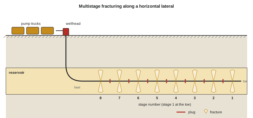
Multistage fracturing of horizontal wells
The combination of long horizontal wells and many fracture stages unlocked tight oil and shale gas in North America after about 2008. In the common plug-and-perforate method, the crew starts at the toe of the lateral. A perforating gun opens a cluster of holes, often several clusters per stage, and the fracture treatment is pumped. Then a plug is set above the stage, the next set of clusters is perforated and the next stage is pumped. A modern well may have 40 to 80 stages. After the last stage, coiled tubing drills out the plugs so the whole lateral can flow. Sliding-sleeve systems, in which balls of increasing size open ports in the liner one stage at a time, avoid wireline runs and are common in some plays.
A typical Tamarack Lake field well has a 10,000 ft lateral fractured in 50 stages about 200 ft apart. Each stage uses roughly 4,000 bbl of slickwater and 200,000 lb of sand, so the whole well takes about 200,000 bbl of water, more than 8 million gallons, and 10 million lb of proppant. Over the years, operators in the Bakken have pumped more proppant per foot, placed stages closer together and drilled longer laterals: the state reported a record average completed lateral of about 13,600 ft in the second quarter of 2026.
# Multistage fracture treatment: stages, water, sand and pumping time (oilfield units)
lateral_ft = 10000
spacing_ft = 200
fluid_per_stage = 4200.0         # bbl
sand_per_stage = 210000.0        # lb
rate = 80.0                      # bbl/min
between_stages_h = 1.5           # wireline plug and perforate run

stages = lateral_ft // spacing_ft
water = stages * fluid_per_stage
sand = stages * sand_per_stage
pump_min = fluid_per_stage / rate
total_h = stages * (pump_min / 60 + between_stages_h)
print(f"Stages: {stages}")
print(f"Water: {water:,.0f} bbl  ({water * 42 / 1e6:.1f} million gallons)")
print(f"Sand: {sand / 1e6:.1f} million lb  (average {sand_per_stage / (fluid_per_stage * 42):.2f} lb per gallon of fluid)")
print(f"Pumping time per stage: {pump_min:.1f} min; whole job about {total_h:.0f} h of operations")
print(f"Sand per foot of lateral: {sand / lateral_ft:,.0f} lb/ft")
trucks = sand / 50000.0          # lb per sand truck
print(f"Sand truckloads at 50,000 lb each: {trucks:.0f}")Stages: 50 Water: 210,000 bbl (8.8 million gallons) Sand: 10.5 million lb (average 1.19 lb per gallon of fluid) Pumping time per stage: 52.5 min; whole job about 119 h of operations Sand per foot of lateral: 1,050 lb/ft Sand truckloads at 50,000 lb each: 210
Fracturing fluids and proppants
Most tight oil and shale wells are now fractured with slickwater: water with a small amount of friction-reducing polymer, which lets it be pumped at high rates through long laterals. Slickwater carries proppant poorly, so treatments use high rates and fine sand. Crosslinked gels, made by linking guar polymer molecules with borate or metal ions, are thick enough to carry large amounts of coarse proppant and are used where wider fractures are wanted. Some operators in water-scarce or water-sensitive rock use energized fluids with nitrogen or carbon dioxide, or hydrocarbon-based fluids. Additives control bacteria, scale, clay swelling and corrosion, and together usually make up less than 1 percent of the fluid.
Proppant ranges from natural quartz sand to resin-coated sand and manufactured ceramic beads. Stronger proppants resist crushing under the closure stress of deep rock. Sand is graded by mesh size: 100-mesh sand is very fine, while 40/70 and 30/50 are coarser. The trend in North America has been toward cheaper local sand, sometimes mined close to the field, in very large volumes.
Worked problem
Sizing a fracture treatment
Marcus plans the northern well with a 10,000 ft lateral and stages 200 ft apart. Each stage will use 4,200 bbl of fluid and 210,000 lb of sand, pumped at 80 bbl/min. How many stages are there, how much water and sand does the well need and how long does each stage take to pump?
Show solution
- Stages: 10,000 / 200 = 50.
- Water: 50 × 4,200 = 210,000 bbl, or 8.8 million gallons.
- Sand: 50 × 210,000 = 10.5 million lb.
- Pumping time per stage: 4,200 / 80 = 52.5 minutes, plus time to set plugs and perforate between stages.
Answer: About 210,000 bbl of water and 10.5 million lb of sand in 50 stages. Moving that volume is a logistics job as big as the fracturing itself; pipelines for water, recycled produced water and sand delivered by rail and conveyor help cut truck traffic.
Risks and safeguards
Hydraulic fracturing raises public concerns, and engineers must understand them. The biggest risk to groundwater is not cracks reaching the surface, because fractures in deep tight rock grow at most a few hundred meters upward and are separated from aquifers by kilometers of rock. The real risks are at the well itself and at the surface: poor cement or failed casing that lets fluids travel up the outside of the well, spills of fluids and chemicals, and improper handling of flowback and produced water. Strong well construction, pressure testing before and during the treatment, and careful fluid handling address them.
Induced seismicity is the other major issue. Fracturing near faults can trigger small earthquakes, and deep injection of large volumes of wastewater caused a sharp rise in felt earthquakes in Oklahoma in the 2010s. North Dakota has seen little induced seismicity, but operators still monitor for it. North Dakota requires operators to report fracturing fluid ingredients to the FracFocus registry, to pressure-test casing before stimulation and to monitor the pressure in the annulus during treatments so that a casing leak is detected immediately.
Flowback is the fluid that returns after the treatment, a mix of fracturing fluid and formation water, sometimes very salty and carrying dissolved metals and naturally occurring radioactive materials. It is separated, measured and either recycled into later treatments or injected into deep disposal wells approved by the regulator. Careful water management is now one of the main ways companies reduce both costs and environmental impact.
Monitoring a fracture treatment
During a treatment, the crew watches the surface pressure, the pumping rate, the proppant concentration and the fluid volumes second by second. The treating pressure tells the engineer how the fracture is growing. A steady pressure suggests normal growth; a sharp rise can mean the fracture has stopped growing or the proppant has bridged in the fracture, a condition called a screen-out, which forces the crew to stop pumping. A sudden drop can mean the fracture has broken into another zone or a neighboring well. After pumping stops, the pressure decline reveals the closure pressure and how quickly fluid leaks into the rock.
Engineers use several tools to learn where the fractures actually went. Microseismic monitoring records the tiny rock failures that occur as the fracture grows, using geophones in a nearby well or at the surface, and maps the cloud of events in three dimensions. Chemical tracers added to individual stages show which stages contribute to production. Fiber-optic cables cemented behind casing measure temperature and acoustic signals along the whole lateral, showing which perforation clusters took fluid. Pressure gauges in neighboring wells detect frac hits, when a new fracture connects to an existing well and can damage its production. Together, these measurements guide decisions about stage spacing, well spacing and treatment size for the next wells.
Completion design keeps evolving. Operators have moved from a few large stages to many smaller ones, from crosslinked gels to slickwater, and from ceramic to local sand. Simultaneous fracturing of two wells on a pad, electric fracturing fleets powered by natural gas or grid power, and real-time design changes based on fiber-optic data are now common. Each change is judged by the same test: does the extra oil or gas recovered pay for the extra cost?
After the treatment, the well is flowed back to recover part of the fracturing water before it goes on production. The flowback rate, its chemistry and the amount of sand returned all tell the engineer something about how the fractures cleaned up and how well the proppant stayed in place.
Common mistakes
MistakeBelieving fractures typically reach drinking-water aquifers.
InsteadDeep fractures grow at most a few hundred meters upward. The main groundwater risks are poor well integrity and surface spills.
MistakeTreating matrix acidizing and hydraulic fracturing as the same.
InsteadAcidizing works below fracture pressure to remove near-well damage; fracturing exceeds fracture pressure to create a propped crack.
MistakeIgnoring the plugs after a plug-and-perforate job.
InsteadPlugs must be drilled out or dissolve before the full lateral can flow.
MistakeAssuming more stages always pay.
InsteadCloser spacing raises cost and can cause fractures to interfere; the best design balances cost against added recovery.
Summary and key terms
- Completion connects the well to the reservoir through open hole or perforated casing, with tubing, packers and a wellhead.
- Matrix acidizing removes near-well damage below fracture pressure; hydraulic fracturing creates propped cracks above it.
- Multistage plug-and-perforate completions of long horizontal wells made tight oil and shale gas economic.
- Slickwater with fine sand dominates tight-rock treatments; gels and energized fluids suit other conditions.
- Main risks are well integrity, surface spills, water handling and induced seismicity, all managed by regulation and monitoring.
- Flowback and produced water are recycled or disposed of in approved deep wells.
- Completion
- The equipment and work that connect a drilled well to the reservoir and prepare it to produce.
- Perforation
- A hole shot through casing and cement into the reservoir by a shaped charge.
- Skin
- A measure of extra pressure drop near the wellbore caused by damage or stimulation.
- Hydraulic fracturing
- Pumping fluid above the rock's fracture pressure to create cracks, propped open with sand or ceramic.
- Proppant
- Sand or ceramic particles that hold a hydraulic fracture open after pumping stops.
- Slickwater
- Water with friction-reducing additives, pumped at high rates in tight-rock fracturing.
- Flowback
- Fluid that returns to the surface after a fracturing treatment.
Practice problems
Work each problem on paper first, then reveal the answer to check.
A 12,000 ft lateral has stages every 240 ft, each using 5,000 bbl of fluid. How many stages and how much fluid?
Show answer
50 stages; 50 × 5,000 = 250,000 bbl.
Why are hydraulic fractures in deep reservoirs usually vertical?
Show answer
They open against the least principal stress, which at depth is usually horizontal, so the fracture plane is vertical.
What is the purpose of the plug in a plug-and-perforate completion?
Show answer
It isolates the stages already treated so the next stage's fluid goes only into the newly perforated clusters.
Name two ways operators reduce the fresh-water use of fracturing.
Show answer
Recycling flowback and produced water, using brackish or saline water, and using energized or alternative fluids.
Lesson quiz · 5 questions
Score 60% or more to complete this lesson.
Create a free account to save your progress, take quizzes and earn a certificate.