
CMP-450 · Lesson 6 of 12 · 24 min
Arithmetic and DSP: fixed-point, pipelined multipliers, FIR
Signal processing is where FPGAs earn their place in most products, and it is the heart of the NS-5 front end. This lesson covers the arithmetic that hardware signal processing is built on: fixed-point number formats and how their widths grow, rounding and saturation, multipliers and how DSP slices pipeline them, and finite impulse response (FIR) filters in the structures that suit FPGAs. It ends with the architecture of the NS-5's decimating filter and a bit-accurate model that becomes its reference.
Each NS-5 receive channel produces 12-bit samples at 2 MS/s. The radar's useful signal lies below about 200 kHz; above that there is interference and noise that would alias into the band if the samples were simply decimated. The filter must therefore remove everything above 250 kHz before the rate is reduced by four to 500 kS/s. Ines has specified a 32-tap linear-phase low-pass filter, at least 40 dB of attenuation above 350 kHz, and an output word of 16 bits.
Fixed-point formats
Floating-point arithmetic is available in FPGAs, but it costs several times the area and latency of fixed-point arithmetic, so signal processing datapaths almost always use fixed point. A fixed-point number is an integer with an implied binary point. In the Qm.n notation used here, a signed value has m integer bits including the sign and n fractional bits, m + n bits in all. Its value is the integer divided by 2^n, its resolution is 2^−n, and its range is:
The NS-5 ADC output is a 12-bit two's complement integer, which the design treats as Q1.11: a value from −1 to just under +1 in steps of 2^−11. The filter coefficients are Q1.15, 16-bit values from −1 to just under 1. Hardware never sees the binary point, only integers; the format is a convention the designer tracks, and keeping track of it through every operation is the main discipline of fixed-point design.
The rules for combining formats follow from integer arithmetic. Adding two Qm.n values needs one extra integer bit to avoid overflow, giving Q(m+1).n. Multiplying Qa.b by Qc.d gives Q(a+c).(b+d): the widths add, and the fractional widths add. Summing N products needs ceil(log2 N) extra integer bits in the worst case. The tighter bound, used when the coefficients are known, is that a filter's output can never exceed the input's maximum times the sum of the absolute values of the coefficients.
Worked problem
Accumulator width for the NS-5 filter
The input is Q1.11 and the coefficients are Q1.15. Using the symmetric form, each product multiplies the sum of two samples by one coefficient. How wide must the products and the accumulator be?
Show solution
- The pre-adder adds two Q1.11 samples, giving Q2.11, 13 bits.
- \[ Q2.11 \times Q1.15 \to Q3.26, \quad 13 + 16 = 29 \text{ bits}\]
- Sixteen such products are summed, so the worst case adds ceil(log2 16) = 4 bits.
- \[ 29 + 4 = 33 \text{ bits}\]
- With the actual coefficients, the sum of their absolute values is about 1.43, so the true bound is 2,048 × 46,880 = 96,010,240 in integer units, which fits in 28 bits signed.
Answer: 29-bit products; 33 bits by the general rule, 28 bits from the coefficient bound. The DSP slice's 48-bit accumulator covers either with room to spare.
Rounding, truncation and saturation
At the end of a computation the wide result must be reduced to the output width, dropping low-order bits. Truncation simply discards them, which in two's complement rounds every value toward minus infinity and introduces a bias of half an output LSB. Round-half-up adds half an LSB before truncating, removing the bias at the cost of one adder. Convergent rounding, also called round-half-even, rounds exact halves to the nearest even value, removing the small remaining bias at halves, which matters in long accumulations and in feedback loops. DSP slices can perform round-half-up for free by preloading the accumulator with the half-LSB constant.
Dropping high-order bits is a different matter. If a result exceeds the output range, wrapping around turns a large positive value into a large negative one, a catastrophic error in a signal. Saturation clamps the value to the maximum or minimum instead, as the offset block of lesson 2 did. A well-designed datapath sizes intermediate results so that overflow cannot occur, and saturates only at the output, where a filter with gain near 1 can slightly exceed full scale on certain inputs.
Every bit dropped adds quantization noise. For a uniformly distributed rounding error of one LSB step q, the noise power is q^2/12, and the signal-to-quantization-noise ratio of a full-scale sine wave in a B-bit format is approximately:
so each extra output bit is worth about 6 dB. A 12-bit ADC gives at most about 74 dB. The NS-5's 16-bit output keeps four bits below the ADC's LSB, so the filter's own rounding adds noise about 24 dB below the ADC's and does not degrade the signal.
Multipliers and DSP slices
A combinational multiplier generates a partial product for each bit of one operand and adds them, using an array or a tree of carry-save adders, with Booth recoding to halve the number of partial products. In an FPGA these structures are built into the DSP slices, and building one from LUTs is rarely worthwhile except for very narrow or constant multiplications. A multiplication by a constant reduces to shifts and additions: multiplying by 10 is (x << 3) + (x << 1), one adder. Synthesis performs this automatically for constants, and the trick is useful when DSP slices run out.
A DSP slice's multiplier is fast only when pipelined. The typical slice has optional registers on its inputs, after the pre-adder, after the multiplier and on the accumulator output. With all of them enabled, each stage has a short path and the slice runs at its maximum rate; with none, the whole multiply-accumulate is one long combinational path. The coding rule is to write the pipeline registers in the RTL, with no reset or with a synchronous reset of the kind the slice supports, so that synthesis can absorb them into the slice.
// MAC engine datapath written so synthesis maps it onto one DSP slice
always_ff @(posedge clk) begin
    a_r  <= x_new;                    // input registers (in the slice)
    d_r  <= x_old;
    b_r  <= coef;
    ad_r <= a_r + d_r;                // pre-adder register: 13-bit sum
    m_r  <= ad_r * b_r;               // multiplier register: 29-bit product
    if (first_m) p_r <= m_r + RND;    // start a new output with the rounding constant
    else         p_r <= p_r + m_r;    // accumulate
end

// output stage: drop 11 bits (rounding is already in p_r), saturate to 16 bits
always_ff @(posedge clk) begin
    if (done_p) begin
        if      (p_r[47:26] != {22{p_r[26]}})  y <= p_r[47] ? 16'sh8000 : 16'sh7FFF;
        else                                     y <= p_r[26:11];
    end
end
Multiplications wider than the slice are built from several slices. A 32 × 32 multiplication splits each operand into halves and sums four partial products, ah × bh × 2^32 + (ah × bl + al × bh) × 2^16 + al × bl, using the dedicated cascade paths between slices for the additions. It costs four slices, or three if the middle terms are computed together, and several cycles of latency. The NS-5 design avoids this by keeping all its products within one slice's 25 × 18 multiplier.
FIR filters
An FIR filter computes each output as a weighted sum of the most recent N input samples:
Its impulse response has finite length, it is always stable, and when the coefficients are symmetric, h[k] = h[N − 1 − k], it has exactly linear phase: every frequency is delayed by the same (N − 1)/2 samples, which preserves the shape of radar pulses. The NS-5 coefficients come from a windowed-sinc design: the ideal low-pass impulse response truncated to 32 taps and multiplied by a Hamming window to control the ripple.
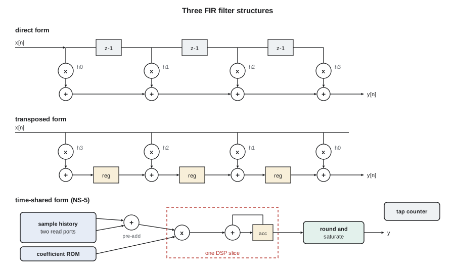
The direct form follows the equation: a delay line of samples, one multiplier per tap and an adder chain. Its adder chain is long, so for high clock rates it is rearranged. The transposed form multiplies each new sample by all coefficients at once and places registers between the adders, so the critical path is one multiply and one add regardless of the number of taps. The systolic form, which DSP slices support with their cascade connections, pipelines the direct form with extra delays in the sample path. These parallel structures produce one output per clock and are right when the sample rate approaches the clock rate.
When the sample rate is far below the clock rate, the time-shared or serial structure is right: one multiplier and accumulator, a memory holding the sample history, a coefficient memory and a counter that steps through the taps. Two refinements cut its work further. Symmetry lets a pre-adder add the two samples that share each coefficient, halving the multiplications. Decimation means only every fourth output is needed, so the filter simply computes outputs at the low rate, which is the simplest form of a polyphase decimator.
The NS-5 filter architecture
Putting the numbers together: four channels at 500 kS/s output need 2 million outputs per second; each output needs 16 multiply-accumulates with the pre-adder, plus 2 cycles of overhead to start and finish, 18 cycles in all. That is 36 million cycles per second, so one MAC engine at 100 MHz is busy 36 % of the time and handles all four channels in turn. The sample history for each channel lives in a small dual-port RAM organized as a circular buffer, so the engine can read the two samples of each symmetric pair in the same cycle.
The latency from the arrival of a channel's newest sample to its filtered output being written is 26 cycles: 2 for the history read, 3 in the slice's input, pre-adder and multiplier registers, 16 accumulation cycles, 1 for the accumulator output register, 2 for rounding and saturation and 2 to reach the frame buffer. The four channels are processed in turn, starting 18 cycles apart, so the fourth channel's output is written 3 × 18 + 26 = 80 cycles after the first channel starts. That is the flush time the capture controller of lesson 3 waits for.
A bit-accurate model
The model below is the filter's specification in executable form. It designs the coefficients, quantizes them to Q1.15 and corrects the rounding so the DC gain is exactly 1, generates a test signal with an in-band tone at 50 kHz and an out-of-band tone at 700 kHz quantized to 12 bits, and filters it with exactly the integer operations of the hardware: 13-bit pre-adds, 29-bit products, a wide accumulator, rounding and saturation. It compares three output formats against the same filter in exact arithmetic, checks the accumulator bound, and measures the filter's effect on both tones.
import math, random

N, FS, DEC = 32, 2.0e6, 4
FC = 0.125                                    # cutoff as a fraction of FS (250 kHz)

# windowed-sinc low-pass design, Hamming window, normalized to unity DC gain
h = []
for n in range(N):
    m = n - (N - 1) / 2
    s = 2 * FC if m == 0 else math.sin(2 * math.pi * FC * m) / (math.pi * m)
    h.append(s * (0.54 - 0.46 * math.cos(2 * math.pi * n / (N - 1))))
g = sum(h)
h = [v / g for v in h]

hq = [round(v * 2**15) for v in h]           # Q1.15 coefficients
d = 2**15 - sum(hq)                          # rounding left the DC gain slightly off
hq[N // 2 - 1] += d // 2; hq[N // 2] += d // 2   # fix it on the two middle taps
print("Q1.15 coefficients h[0..15]:", hq[:16])
print(f"symmetric: {hq == hq[::-1]},  sum = {sum(hq)} (2^15 = {2**15}),  max |h| = {max(map(abs, hq))}")

# test input: 50 kHz in band, 700 kHz out of band, a little noise; 12-bit ADC
random.seed(6)
L = 4096
xf = [0.55 * math.sin(2 * math.pi * 50e3 * k / FS) + 0.3 * math.sin(2 * math.pi * 700e3 * k / FS)
      + random.gauss(0, 0.002) for k in range(L)]
x = [max(-2048, min(2047, round(v * 2048))) for v in xf]     # Q1.11 integers

def fir_fixed(x, hq, out_frac=4, rnd=True):
    """bit-accurate model: 12x16-bit products, wide accumulator, round to 16 bits"""
    y, acc_max = [], 0
    sh = 15 - out_frac                       # keep out_frac fraction bits beyond the input LSB
    for n in range(N - 1, len(x)):
        acc = 0
        for k in range(N // 2):              # symmetric: pre-add the two samples sharing h[k]
            pre = x[n - k] + x[n - (N - 1) + k]          # 13-bit pre-adder result
            acc += pre * hq[k]                           # 13 x 16 = 29-bit product
        acc_max = max(acc_max, abs(acc))
        v = (acc + (1 << (sh - 1))) >> sh if rnd else acc >> sh
        y.append(max(-2**15, min(2**15 - 1, v)))         # saturate to 16 bits
    return y, acc_max

def fir_float(x, h):
    return [sum(h[k] * x[n - k] for k in range(N)) for n in range(N - 1, len(x))]

yr = fir_float(x, [c / 2**15 for c in hq])   # same coefficients, exact arithmetic
for label, frac, rnd in [("16-bit output, rounded", 4, True),
                         ("12-bit output, rounded", 0, True),
                         ("12-bit output, truncated", 0, False)]:
    yq, amax = fir_fixed(x, hq, frac, rnd)
    err = [a / 2**frac - b for a, b in zip(yq, yr)]
    p_sig = sum(b * b for b in yr) / len(yr)
    p_err = sum(e * e for e in err) / len(err)
    mean = sum(err) / len(err)
    print(f"{label:25s} SNR {10 * math.log10(p_sig / p_err):5.1f} dB   mean error {mean:+.3f} LSB")
bound = 2048 * sum(abs(c) for c in hq)
print(f"largest |accumulator| seen = {amax} ({amax.bit_length() + 1} bits signed); "
      f"worst-case bound = {bound} ({bound.bit_length() + 1} bits signed)")

def tone_level(y, f):
    """amplitude of the component at frequency f, by correlation"""
    c = sum(v * math.cos(2 * math.pi * f * k / FS) for k, v in enumerate(y))
    s = sum(v * math.sin(2 * math.pi * f * k / FS) for k, v in enumerate(y))
    return 2 * math.hypot(c, s) / len(y)

yq, _ = fir_fixed(x, hq)
for f in (50e3, 700e3):
    a_in, a_out = tone_level(x, f), tone_level([v / 16 for v in yq], f)
    print(f"{f/1e3:5.0f} kHz: in {a_in:7.1f} LSB  out {a_out:7.2f} LSB  gain {20 * math.log10(a_out / a_in):6.1f} dB")

def resp_db(c, f):
    re_ = sum(v * math.cos(2 * math.pi * f * n / FS) for n, v in enumerate(c))
    im_ = sum(v * math.sin(2 * math.pi * f * n / FS) for n, v in enumerate(c))
    return 20 * math.log10(math.hypot(re_, im_))
for f in (350e3, 700e3):
    print(f"response at {f/1e3:.0f} kHz: ideal coefficients {resp_db(h, f):6.1f} dB, "
          f"Q1.15 coefficients {resp_db([c / 2**15 for c in hq], f):6.1f} dB")

# decimation: computing only every fourth output gives the same samples
yd = yq[::DEC]
print(f"decimated output: {len(yd)} samples at {FS / DEC / 1e3:.0f} kS/s, first five: {yd[:5]}")Q1.15 coefficients h[0..15]: [-21, -60, -84, -52, 78, 273, 387, 221, -301, -974, -1305, -731, 1017, 3642, 6306, 7988] symmetric: True, sum = 32768 (2^15 = 32768), max |h| = 7988 16-bit output, rounded SNR 92.9 dB mean error -0.000 LSB 12-bit output, rounded SNR 68.9 dB mean error +0.002 LSB 12-bit output, truncated SNR 62.8 dB mean error -0.502 LSB largest |accumulator| seen = 37143256 (27 bits signed); worst-case bound = 96010240 (28 bits signed) 50 kHz: in 1127.2 LSB out 1130.72 LSB gain 0.0 dB 700 kHz: in 614.5 LSB out 0.23 LSB gain -68.5 dB response at 350 kHz: ideal coefficients -43.1 dB, Q1.15 coefficients -42.9 dB response at 700 kHz: ideal coefficients -72.5 dB, Q1.15 coefficients -75.1 dB decimated output: 1017 samples at 500 kS/s, first five: [11746, 1416, -9447, -16719, -17608]
The results confirm each design decision. The 16-bit rounded output has a signal-to-noise ratio of about 93 dB against exact arithmetic, so the datapath's own error is negligible next to the ADC's. Rounding to 12 bits instead would give about 69 dB, which matches the 6 dB-per-bit rule for this signal level, and truncating to 12 bits adds a bias of half an LSB, the mean error of −0.502. The largest accumulator value seen is within 27 bits, under the 28-bit worst-case bound. The 50 kHz tone passes with 0.0 dB of gain, while the 700 kHz tone is attenuated by over 68 dB, to the level of the added noise. The quantized coefficients still give about 43 dB of attenuation at 350 kHz, meeting the 40 dB specification.
Every number this model prints will reappear in the hardware testbench. The model writes its input and output samples as vectors, the RTL filter processes the same input, and the scoreboard requires the outputs to match exactly, bit for bit. A difference of one LSB in one sample is a bug: either the model or the RTL has rounded, ordered or saturated differently, and it must be found before the bitstream ships.
Other arithmetic in FPGAs
A few other techniques complete the designer's toolkit. CORDIC computes rotations, magnitudes, phases and trigonometric functions with shifts and additions only, one bit per iteration, and suits FPGAs without many multipliers. Distributed arithmetic precomputes sums of coefficients in LUTs and processes inputs one bit at a time, replacing multipliers with lookups. Block floating point shares one exponent among a block of samples, which is common in fast Fourier transforms, where the dynamic range grows with each stage. And infinite impulse response filters, with feedback, achieve sharp responses with far fewer coefficients but need careful attention to coefficient quantization, stability and limit cycles; for the NS-5's linear-phase requirement, the FIR is the right choice.
Common mistakes
MistakeLosing track of the binary point through multiplications and sums.
InsteadWrite the Qm.n format of every signal and apply the width rules at each operation.
MistakeTruncating results and ignoring the bias.
InsteadRound, ideally by preloading the accumulator with half an LSB, and use convergent rounding in long accumulations.
MistakeLetting intermediate values wrap on overflow.
InsteadSize intermediate widths from the bounds so overflow cannot occur, and saturate at the output.
MistakeWriting multipliers without pipeline registers.
InsteadCode the input, multiplier and accumulator registers so they map into the DSP slice.
MistakeBuilding a parallel filter when the clock is many times the sample rate.
InsteadTime-share one MAC engine, using symmetry and decimation to cut the work.
Summary and key terms
- Fixed-point Qm.n values are integers with an implied binary point; adding needs one extra bit and multiplying adds the widths.
- Sums of N products need up to ceil(log2 N) guard bits; the coefficient bound is often tighter.
- Round rather than truncate, size intermediates to avoid overflow and saturate at the output.
- SQNR is about 6.02B + 1.76 dB; keeping extra output bits keeps filter noise below the ADC noise.
- DSP slices run fast only with their pipeline registers enabled.
- FIR structures range from fully parallel to time-shared; the NS-5 uses one symmetric MAC engine at 36 % load with 26 cycles of latency.
- Fixed point
- A number representation as an integer scaled by a fixed power of two.
- Qm.n format
- A signed fixed-point format with m integer bits including the sign and n fractional bits.
- Guard bits
- Extra high-order bits in an accumulator that prevent overflow during summation.
- Saturation
- Clamping a result to the largest or smallest representable value instead of letting it wrap.
- Convergent rounding
- Rounding to nearest with exact halves rounded to the even value, removing bias.
- FIR filter
- A filter whose output is a weighted sum of a finite number of past inputs.
- Linear phase
- A property of symmetric FIR filters in which every frequency is delayed by the same time.
- Polyphase decimator
- A filter structure that computes only the outputs retained after rate reduction.
Practice problems
Work each problem on paper first, then reveal the answer to check.
What format results from multiplying Q1.11 by Q1.15, and how many bits is it?
Show answer
Q2.26, 28 bits.
How much SQNR does a 14-bit format give for a full-scale sine?
Show answer
6.02 × 14 + 1.76 ≈ 86 dB.
How many cycles per output would the NS-5 engine need without the pre-adder?
Show answer
32 MACs plus 2 overhead = 34 cycles, giving 68 % load at 100 MHz.
Write x × 20 with shifts and one addition.
Show answer
(x << 4) + (x << 2).
Lesson quiz · 5 questions
Score 60% or more to complete this lesson.
Create a free account to save your progress, take quizzes and earn a certificate.