
CIV-340 · Lesson 1 of 12 · 24 min
Soil origins and site investigation
Every structure in this program, from the reinforced concrete office block to the steel maintenance bay, ends at a footing that pushes on the ground. Soil mechanics is the study of how that ground behaves: how much water it holds, how it compacts, how water flows through it, how it compresses under load and how strong it is. This course works through those questions for the Kestrel Bay operations center in Duluth, where the CIV-330 footings, the CIV-331 steel bay and a new pump station must all be founded on soils left behind by glaciers and glacial lakes. The first lesson explains where soils come from and how engineers find out what is under a site.
Why soil is different
Steel and concrete are manufactured to a specification, tested in the plant and delivered with a mill certificate. Soil is not. It was made by weathering, moved by ice, water and wind, and laid down in layers that vary across a site and with depth. The engineer cannot choose the soil, only discover it, and the discovery is always incomplete: a borehole samples a column of soil a few centimeters wide, and the ground between boreholes is inferred.
Soil is also a three-phase material. It is a skeleton of mineral grains with pores between them, and the pores are filled with water, air or both. Much of what makes soil interesting comes from that arrangement. When load is applied, the grains rearrange and the pores shrink, but water must flow out of the pores before they can shrink. In a clean sand the water escapes in seconds; in a clay it can take years. The strength of soil comes from friction and interlocking between grains, and that friction depends on how hard the grains are pressed together, which in turn depends on the water pressure in the pores. These ideas, effective stress, consolidation and drained versus undrained behavior, run through the whole course.
How soils form
Soils begin as rock. Physical weathering, such as frost wedging, abrasion and the unloading of rock as overlying material erodes, breaks rock into fragments without changing its minerals. Chemical weathering, such as hydrolysis and oxidation, changes the minerals themselves, turning feldspars and micas into clay minerals. The products of weathering are either left in place as residual soils or carried away and deposited as transported soils.
In most of Canada and the northern United States, the soils engineers deal with are young and transported. Continental ice sheets covered the region repeatedly, the last retreat ending roughly ten thousand years ago. The ice left several distinctive deposits:
- Till, deposited directly by the ice, is a mixture of every particle size from clay to boulders. Till lodged under the moving ice was pressed by its great weight and is usually very dense and stiff.
- Glaciofluvial deposits, laid down by meltwater rivers, are sands and gravels sorted by the flowing water into layers of similar size.
- Glaciolacustrine deposits settled out in lakes dammed by the ice. Silts and clays accumulated on the lake floor, often in varves: pairs of thin layers, a coarser summer layer and a finer winter layer.
- Later processes added beach and dune sands along shorelines, river alluvium in valleys, and organic soils such as peat in poorly drained hollows.
The Duluth site sits on the floor of glacial Lake Duluth and the later lakes that occupied the western end of the Lake Superior basin as the ice withdrew. The CIV-241 desk study predicted a sequence that is common along the shore: several feet of sand reworked by waves and rivers as the lake levels fell, over gray varved glaciolacustrine silty clay, over dense till, over volcanic bedrock.
Soil grains and clay minerals
Coarse soils, gravels and sands, are made of rock fragments and resistant minerals such as quartz, roughly equidimensional and visible to the eye. Their behavior depends mostly on grain size, shape and how densely the grains are packed. Fine soils include silts, which are tiny rock flour, and clays, which are dominated by platy clay minerals a few micrometers or less across. Clay minerals carry negative electric charges on their faces, attract water and cations, and give clays their plasticity: the ability to be molded without crumbling. Kaolinite is the least active clay mineral, illite is intermediate, and smectites such as montmorillonite swell strongly when wet. Glacial lake clays in the Lake Superior basin are mostly illite and finely ground quartz and feldspar, so they are plastic but not highly expansive.
Planning a site investigation
A site investigation finds out what soils and rock are present, where they are, how they behave and where the groundwater is. It proceeds in stages. A desk study reviews geological maps, air photos, lidar, previous borehole logs and the history of the site. A site reconnaissance looks for evidence on the ground: seepage, slope movements, cracked pavements, old fill. Then a subsurface investigation drills boreholes, pushes probes, takes samples and installs instruments, and a laboratory program tests the samples.
How many boreholes are needed depends on the size of the structure, the variability of the ground and the consequences of being wrong. A common guide for buildings is one borehole for each major footing group or roughly every 15 to 30 m (50 to 100 ft) across the footprint, with more where the soil changes. Boreholes must go deep enough to pass through all soil that the structure will stress significantly. A rule of thumb is to drill to at least one and a half to two times the footing width below the footing, and through any compressible layer to a competent stratum.
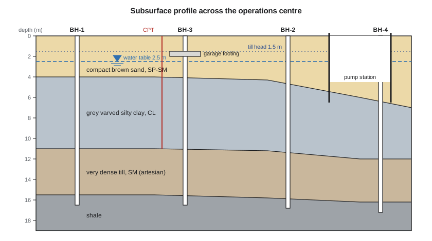
For the operations center, Dr. Lena Kowalczyk, P.E., the geotechnical engineer at Kestrel Bay Engineering, laid out four borings and two cone penetration tests across the garage, office and pump station areas. Owen Lachance, EI, who designed the footings in CIV-330, joins her for the fieldwork, and Sofia Martel, the co-op student, writes the Python tools used to reduce the data.
Drilling and sampling
Most geotechnical boreholes are drilled with hollow-stem augers, which carry soil up the spiral flights while the hollow center stays open for sampling, or by mud rotary or sonic drilling where augers cannot advance. At intervals, the drill crew stops and takes a sample from the bottom of the hole. Samples are disturbed or undisturbed. A disturbed sample keeps the soil's grain size and water content but not its structure; it is good enough for classification. An undisturbed sample, taken by pushing a thin-walled steel tube (a Shelby tube) into soft or firm clay, keeps the structure well enough for consolidation and strength tests.
Every sample is described in the field, labeled, sealed to keep its moisture and taken to the laboratory. The driller and the engineer also record the depth to groundwater when it first appears, at the end of drilling and, if a standpipe piezometer is installed, days or weeks later, after the water level has stabilized. In clay, water levels can take a long time to equalize, so one reading at the end of drilling may mislead.
The standard penetration test
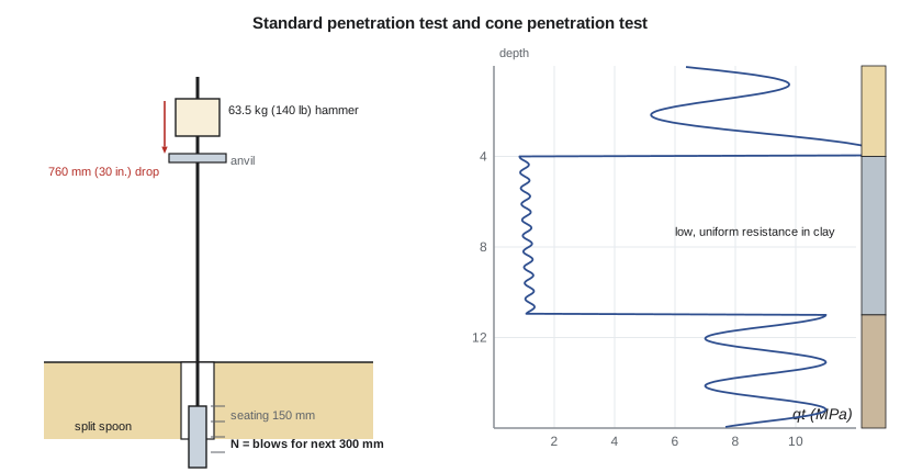
The standard penetration test (SPT) is the most common in situ test in North America. A split-spoon sampler, a thick-walled tube 51 mm (2 in.) in outside diameter, is driven into the bottom of the borehole by a 63.5 kg (140 lb) hammer falling 760 mm (30 in.). The number of blows to drive it the second and third 150 mm (6 in.) increments is the N value, in blows per 300 mm (blows per foot). The sampler also recovers a disturbed sample.
The SPT is crude but cheap, and decades of experience link N values to the density of sands and, more loosely, to many design parameters. Its main weakness is variability in the energy that the hammer delivers. Old rope-and-cathead hammers deliver around 60 % of the theoretical free-fall energy, while modern automatic hammers deliver 70 to 95 %. Results are therefore normalized to 60 % energy:
where \(E_r\) is the measured energy ratio in percent. Smaller corrections for rod length, borehole diameter and sampler liners are often applied too. Because N in a given sand increases with confining stress, it is further normalized to an effective overburden stress of one atmosphere:
The effective vertical stress \(\sigma'_v\) is the stress carried by the grains, which lesson 6 develops in detail; here it is the weight of soil above the test point minus the water pressure. The normalized value correlates with relative density, the subject of lesson 2, and with the friction angle of the sand.
The cone penetration test
The cone penetration test (CPT) pushes an instrumented steel cone with a 60° tip and a 10 cm² base into the ground at a steady 20 mm/s. It measures the resistance on the tip, \(q_c\), the friction on a sleeve behind the tip, \(f_s\), and in the piezocone (CPTu), the pore water pressure \(u_2\) just behind the cone. Readings every few centimeters give a nearly continuous profile, so thin layers that an SPT every 1.5 m (5 ft) would miss show up clearly. The tip resistance corrected for pore pressure is \(q_t\). The ratio \(f_s/q_t\), the friction ratio, is high in clays and low in sands and is the basis of soil behavior type charts.
The CPT recovers no sample, so it is paired with boreholes. In clay, its readings give the undrained shear strength through an empirical cone factor:
where \(\sigma_v\) is the total vertical stress and \(N_{kt}\) usually lies between about 10 and 20; it is calibrated locally against field vane or laboratory tests. The field vane test itself rotates a four-bladed vane in clay at the bottom of a borehole and measures the torque needed to shear a cylinder of soil.
Reducing the B-3 data
Boring B-3, at the garage, found 1 ft of topsoil, brown fine to medium sand with some silt to 13 ft, gray varved silty clay to 36 ft, very dense gray silty sand till to 51 ft and then basalt. Groundwater stabilized at 8 ft in an observation well. The automatic hammer on the drill rig had a measured energy ratio of 80 %. The CPT next to B-3 and four field vane tests characterized the clay.
Worked problem
Normalizing an SPT result
At 10 ft in B-3 the field blow count is \(N = 15\). The sand weighs 115 pcf above the water table at 8 ft and 126 pcf below. Find \(N_{60}\) and \((N_1)_{60}\).
Show solution
- Energy correction for the 80 % hammer:
- \[N_{60} = 15 \times \frac{80}{60} = 20.0\]
- Effective stress at 10 ft, with 2 ft of soil below the water table:
- \[\sigma'_v = 115(8) + 126(2) - 62.4(2) = 1047\ \text{psf}\]
- \[C_N = \sqrt{2117/1047} = 1.42 \qquad (N_1)_{60} = 1.42(20.0) = 28.4\]
Answer: With \(N_{60} = 20\) the sand is medium dense, and \((N_1)_{60} \approx 28\) suggests a relative density of roughly 70 %.
Sofia's script applies the same steps to every SPT in the sand and reduces the CPT readings in the clay. The density descriptions follow the usual bands on \(N_{60}\), and the relative density uses a simple square-root correlation for clean sand.
# Borehole B-3, Kestrel Bay operations center: SPT in the sand, CPT in the clay
from math import sqrt
ER = 80.0                        # measured hammer energy ratio (%) for the automatic hammer
gw = 8.0                         # groundwater depth (ft)
gm, gs = 115.0, 126.0            # sand unit weight above / below groundwater (pcf)
gw_unit = 62.4
Pa = 2117.0                      # atmospheric pressure (psf)

def sigma_v(z):
    """Total and effective vertical stress in the sand (psf)."""
    s = gm * min(z, gw) + gs * max(z - gw, 0)
    u = gw_unit * max(z - gw, 0)
    return s, s - u

def describe(n60):
    for lim, name in ((4, "very loose"), (10, "loose"), (30, "medium dense"), (50, "dense")):
        if n60 < lim:
            return name
    return "very dense"

print(" depth   N   N60  s'v(psf)  CN   (N1)60  Dr(%)  description")
for z, N in ((2.5, 9), (5.0, 12), (7.5, 14), (10.0, 15), (12.5, 18)):
    n60 = N * ER / 60
    s, sp = sigma_v(z)
    cn = min(1.7, sqrt(Pa / sp))
    n160 = cn * n60
    dr = 100 * sqrt(n160 / 60)            # Skempton-type estimate for clean sand
    print(f"{z:5.1f} {N:4d} {n60:5.1f} {sp:8.0f} {cn:5.2f} {n160:7.1f} {dr:6.0f}   {describe(n60)}")

# CPT in the clay: undrained shear strength su = (qt - sigma_v) / Nkt
Nkt = 15
s13 = sigma_v(13.0)[0]           # total stress at the top of the clay
print("\n depth  qt(tsf)  sigma_v(psf)  su CPT(psf)  su vane(psf)")
for z, qt, vane in ((16.5, 11.0, 1210), (21.5, 10.7, 1090), (26.0, 11.5, 1150), (31.0, 12.6, 1250)):
    sv = s13 + 113.0 * (z - 13.0)
    su = (qt * 2000 - sv) / Nkt
print(f"{z:5.1f} {qt:7.1f} {sv:12.0f} {su:12.0f} {vane:12d}")depth N N60 s'v(psf) CN (N1)60 Dr(%) description 2.5 9 12.0 288 1.70 20.4 58 medium dense 5.0 12 16.0 575 1.70 27.2 67 medium dense 7.5 14 18.7 862 1.57 29.2 70 medium dense 10.0 15 20.0 1047 1.42 28.4 69 medium dense 12.5 18 24.0 1206 1.32 31.8 73 medium dense depth qt(tsf) sigma_v(psf) su CPT(psf) su vane(psf) 16.5 11.0 1946 1337 1210 21.5 10.7 2510 1259 1090 26.0 11.5 3019 1332 1150 31.0 12.6 3584 1441 1250
The sand is medium dense throughout, and the shallow values reach the 1.7 cap on \(C_N\), which prevents unrealistic corrections at low stress. In the clay, the CPT with \(N_{kt} = 15\) gives \(s_u\) of about 1,260 to 1,440 psf, slightly above the vane values of 1,090 to 1,250 psf. Dr. Kowalczyk will calibrate \(N_{kt}\) to the vane, about 17 here, and adopt a design profile near 1,150 psf for the medium stiff to stiff clay.
The borehole log
Each borehole is summarized on a log: a vertical strip showing the depth, a graphic symbol and a description for each stratum, the sample numbers and types, the SPT N values, water contents and other test results, and the groundwater observations. Soil descriptions follow a standard order so that anyone can read them: the principal soil type, secondary components, color, moisture, density or consistency, structure and geological origin. A typical description of the clay at the garage reads: silty clay, trace sand, gray, moist, firm to stiff, varved, glaciolacustrine.
In US practice, ASTM D2488 sets out the procedure for visual-manual description of soils, and agencies such as the FHWA and state DOTs publish logging manuals. Coarse soils are described as very loose, loose, medium dense, dense or very dense, and fine soils as very soft, soft, medium stiff, stiff, very stiff or hard, based on N values and undrained strength.
| Consistency of clay | su (psf) | Field feel |
|---|---|---|
| Very soft | < 250 | Extrudes between the fingers when squeezed |
| Soft | 250–500 | Molded by light finger pressure |
| Medium stiff | 500–1,000 | Molded by strong finger pressure |
| Stiff | 1,000–2,000 | Indented by the thumb with effort |
| Very stiff | 2,000–4,000 | Indented by the thumbnail |
| Hard | > 4,000 | Difficult to indent by the thumbnail |
Groundwater
Groundwater controls almost everything in soil mechanics. It reduces the effective stress and therefore the strength and stiffness of soil, it flows into excavations, it can lift slabs and tanks, and it freezes. A site investigation must establish the water level, its seasonal range and whether there are layers with different heads. The operations center adds one more concern: the site is close to Lake Superior, so the water table in the sand is connected to the lake and rises in spring.
Frost
Duluth has a long, cold winter, and frost penetrates deeply into bare, snow-cleared ground. Silty soils with access to water can form ice lenses and heave. Minnesota's building code requires footings in the northern frost zone, which includes St. Louis County, to be at least five feet below grade, and the CIV-330 footings were placed with their bases at 5 ft. Unheated structures such as the salt shed need the same depth or insulation. Lesson 3 explains why the silt content of the sand matters for frost.
Factual and interpretive reports
The results of an investigation are reported in two parts. A factual report presents the logs, test results and groundwater readings without interpretation. An interpretive report, the geotechnical report, gives the engineer's model of the ground, design parameters and recommendations for foundations, excavations, dewatering and earthworks. Keeping the two apart lets contractors rely on the facts while the interpretation stays with the engineer. Lesson 12 assembles the soils report for the operations center from the results of every lesson.
Practical points
- Never design from one borehole. Soil varies, and the variation is often the main risk.
- Record groundwater in standpipes after it stabilizes, not only at the end of drilling.
- Always state the hammer type and energy ratio with SPT results, and normalize before using correlations.
- Use the CPT for continuous profiles and the boreholes for samples; each fills the other's gaps.
- Take undisturbed tube samples in clay that will be tested for consolidation or strength, and keep them upright and protected from freezing.
Common mistakes
MistakeUsing raw N values from different hammers as if they were comparable.
InsteadNormalize to N60 using the measured energy ratio.
MistakeApplying sand correlations, such as relative density, to N values in clay.
InsteadUse N in clay only as a rough guide; measure su with vanes, the CPT or laboratory tests.
MistakeStopping boreholes at a shallow depth because the soil looks good.
InsteadDrill through every compressible layer the structure will stress, to a competent stratum.
MistakeReporting the water level at the end of drilling as the groundwater level.
InsteadInstall a piezometer and read it after the level has stabilized.
Summary and key terms
- Most soils in glaciated regions are young transported deposits: till, glaciofluvial sand and gravel, and glaciolacustrine silt and clay.
- Soil is a three-phase material whose behavior depends on the grains, the pore water and the stress between grains.
- A site investigation proceeds from desk study and reconnaissance to boreholes, in situ tests, sampling and laboratory testing.
- SPT blow counts are normalized for energy, \(N_{60} = N E_r/60\), and for overburden, \((N_1)_{60} = C_N N_{60}\).
- The CPT gives continuous profiles; in clay \(s_u = (q_t - \sigma_v)/N_{kt}\), with \(N_{kt}\) calibrated locally.
- B-3 found medium dense sand to 13 ft, medium stiff to stiff clay with su near 1,150 psf to 36 ft, and very dense till, with groundwater at 8 ft.
- Till
- Soil deposited directly by glacier ice, usually a dense mixture of all particle sizes.
- Glaciolacustrine
- Deposited in a lake formed by glacial meltwater, typically silt and clay.
- Varve
- A pair of annual layers, coarser in summer and finer in winter, in a glacial lake deposit.
- Standard penetration test
- A test that counts hammer blows to drive a split-spoon sampler 300 mm (1 ft).
- Energy ratio
- The fraction of the theoretical free-fall energy that the SPT hammer delivers to the rods.
- Cone penetration test
- A test that pushes an instrumented cone and records tip resistance, sleeve friction and pore pressure.
- Shelby tube
- A thin-walled steel tube pushed into clay to recover a relatively undisturbed sample.
- Piezometer
- An instrument that measures the pore water pressure or water level at a point in the ground.
Practice problems
Work each problem on paper first, then reveal the answer to check.
An SPT at 5 ft in sand with a donut hammer of 45 % energy ratio gives N = 16. Find N60.
Show answer
\(N_{60} = 16(45/60) = 12\).
A CPT in clay at 23 ft gives qt = 12 tsf where the total stress is 2,700 psf. With Nkt = 17, find su.
Show answer
\(s_u = (24{,}000 - 2{,}700)/17 = 1{,}250\) psf, a stiff clay.
Why is till usually denser and stiffer than glaciolacustrine clay of similar depth?
Show answer
Lodgement till was compacted under the weight of moving ice, so it is heavily overconsolidated; lake clays settled gently through water.
Why might a CPT detect a thin sand seam in clay that a borehole with SPTs every 1.5 m (5 ft) misses?
Show answer
The CPT records nearly continuously, while SPTs sample only short intervals between gaps.
Lesson quiz · 5 questions
Score 60% or more to complete this lesson.
Create a free account to save your progress, take quizzes and earn a certificate.