
CIV-250 · Lesson 9 of 12 · 25 min
Datums, map projections and coordinate systems
A coordinate is only meaningful when everyone agrees on what it is measured from. Two surveyors can locate the same monument perfectly and still report coordinates that differ by a meter or more if one uses an older datum, a different projection, or a different foot. As GNSS, GIS and digital design have made it easy to combine data from many sources, understanding reference systems has become one of the most practical skills in geomatics. This lesson explains the shape of the Earth and the surfaces used to describe it, horizontal and vertical datums in Canada and the United States, map projections and their scale distortions, the difference between ground and grid distances, and the modernization of the national reference systems now under way.
Three surfaces: terrain, geoid and ellipsoid
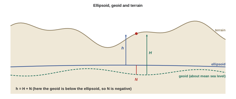
Surveyors work with three different surfaces. The terrain is the physical ground. The geoid is the equipotential surface of the Earth's gravity field that best fits mean sea level; it is the surface a still ocean would follow if extended under the continents, and it is the surface to which a level bubble is perpendicular everywhere. Because the Earth's mass is unevenly distributed, the geoid is bumpy, rising and falling by up to about 100 m relative to a smooth mathematical shape. The ellipsoid is that smooth shape: an ellipse rotated about the Earth's polar axis, slightly flattened at the poles, with a semi-major axis of about 6,378 km and a semi-minor axis about 21 km shorter. The GRS80 ellipsoid is used for NAD83 and is essentially identical to the WGS84 ellipsoid used by GPS.
Heights are measured from either surface. The ellipsoid height \(h\) is measured from the ellipsoid along the normal to it, and it is what GNSS measures directly. The orthometric height \(H\), the ordinary elevation, is measured from the geoid along the direction of gravity. The difference between them is the geoid height or geoid undulation \(N\), the height of the geoid above the ellipsoid:
Across most of the United States and Canada the geoid lies below the ellipsoid, so \(N\) is negative; in central Montana it is roughly −15 m. A GNSS receiver at the Coulee Ridge site therefore reports an ellipsoid height about 15 m smaller than the elevation. Converting between the two requires a geoid model, published by the National Geodetic Survey for the United States.
Worked problem
Elevation from a GNSS ellipsoid height
A GNSS observation on benchmark BM-8 gives an ellipsoid height of 897.53 m in NAD83(2011). The geoid model gives a geoid height of −15.30 m at the point. Find the elevation and compare it with the leveled elevation of 912.839 m.
Show solution
- \[H = h - N = 897.53 - (-15.30) = 912.83\ \text{m}\]
- The GNSS-derived elevation differs from the leveled value by about 1 cm.
Answer: The GNSS-derived elevation is 912.83 m. A difference of about 1 cm is typical of a good GNSS height combined with a modern geoid model, and it shows why leveling is still used where millimeters matter.
Horizontal datums
A geodetic datum defines the origin, orientation and scale of the coordinate system and the ellipsoid used with it. In practice, a datum is realized by a network of monuments and permanent GNSS stations with published coordinates.
The North American Datum of 1927 (NAD27), based on the Clarke 1866 ellipsoid and a single origin in Kansas, was used for most mapping in the mid-twentieth century. It was replaced by the North American Datum of 1983 (NAD83), based on GRS80 and centered approximately at the Earth's center of mass. Coordinates of the same point in NAD27 and NAD83 differ by tens to over a hundred meters, so the datum must be identified for any old coordinates.
NAD83 has been refined several times as GNSS made more accurate measurement possible, and each refinement, called a realization, is identified in parentheses. NAD83 is tied to the North American tectonic plate, so coordinates of points on stable parts of the continent change very little over time. Global frames such as the International Terrestrial Reference Frame (ITRF), and WGS84 which closely follows it, are tied to the Earth as a whole; in those frames, points in North America move by roughly 2 cm per year as the plate drifts. Coordinates in a global frame therefore need a date, called the epoch, as well as a datum.
The United States currently uses NAD83(2011), epoch 2010.00, realized through the National Spatial Reference System (NSRS). The National Geodetic Survey maintains the NSRS, including the network of Continuously Operating Reference Stations (CORS), and its online service, OPUS, processes GNSS observations and returns NAD83(2011) and ITRF coordinates.
Vertical datums
The current official US vertical datum is the North American Vertical Datum of 1988 (NAVD 88), realized by a continental network of leveled benchmarks held to one tide station. NAVD 88 is known to contain errors of tens of centimeters to more than a meter across the country, and many benchmarks have been disturbed or have subsided. The older NGVD 29 still appears on older drawings and flood maps; it differs from NAVD 88 by amounts that vary by region, often by several decimeters to about a meter, so a benchmark's datum must always be confirmed. NAVD 88 is to be replaced by a geoid-based datum, as described below.
Modernization of the reference systems
The National Geodetic Survey is replacing NAD83 and NAVD 88 with a modernized NSRS. The North American Terrestrial Reference Frame of 2022 (NATRF2022), aligned with ITRF, will replace NAD83 and will shift coordinates by roughly 1 to 2 m horizontally and up to a few meters in ellipsoid height. The North American-Pacific Geopotential Datum of 2022 (NAPGD2022), defined by a gravity-based geoid model, will replace NAVD 88, changing elevations by amounts that vary across the country, typically several decimeters to about a meter. A new State Plane Coordinate System of 2022 (SPCS2022) will accompany them. NGS released beta versions of the new frames and tools on September 15, 2026, for a testing period of about six months, after which it plans to review feedback and approve the modernized system. Until then, NAD83(2011) and NAVD 88 remain official, and every coordinate list should state which system it uses.
Map projections
Engineering computations are much easier on a flat grid than on an ellipsoid. A map projection is a mathematical transformation from latitude and longitude to grid coordinates, northing and easting. No projection can flatten a curved surface without distortion, but conformal projections preserve shape locally, so angles measured on the ground equal angles on the grid. Their scale varies from place to place, and that variation is described by the point scale factor \(k\): a distance on the ellipsoid multiplied by \(k\) gives the distance on the grid.
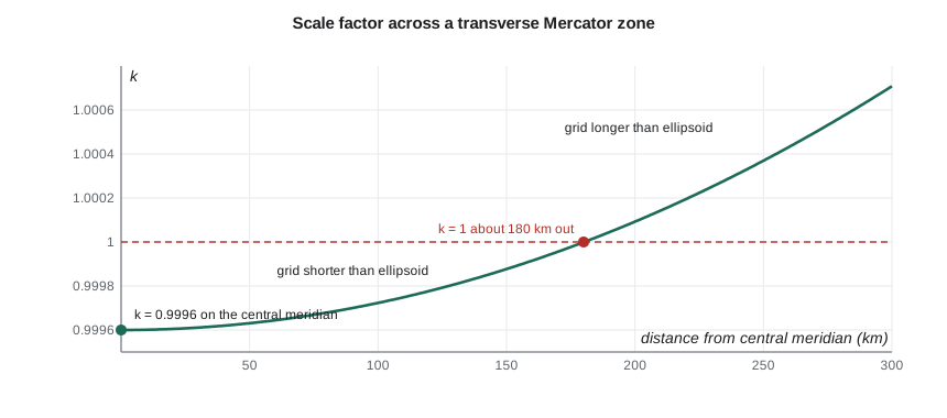
Two conformal projections dominate North American surveying. The transverse Mercator projection wraps a cylinder around the Earth touching along a central meridian, and it suits zones that are long north–south. The Lambert conformal conic projection uses a cone touching or cutting the Earth along standard parallels, and it suits zones that are long east–west. In both, the scale factor is less than 1 in the middle of the zone and greater than 1 near its edges, and zone widths are chosen so that distortion stays within acceptable limits.
The State Plane Coordinate System (SPCS) defines one or more zones for each state, using transverse Mercator or Lambert conformal conic projections, so that distortion within a zone is generally no more than about 1 part in 10,000. Montana uses a single Lambert conformal conic zone for the whole state, with standard parallels at 45° N and 49° N. Montana is one of the states whose law specified the international foot for State Plane coordinates in feet. The Universal Transverse Mercator (UTM) system, with 6° zones and a central scale factor of 0.9996, is also widely used for federal mapping and GIS; Great Falls lies in UTM zone 12.
Grid and ground distances
A horizontal distance measured with a total station at the project's elevation is a ground distance. To use it in grid computations, it must be reduced to the ellipsoid and then scaled to the projection. The elevation factor accounts for the height of the ground above the ellipsoid, and the grid scale factor accounts for the projection. Their product is the combined scale factor:
where \(R\) is the Earth's mean radius, about 6,371 km, and \(h\) is the ellipsoid height of the site. At high elevations the elevation factor is significant: at an ellipsoid height of 900 m, ground distances are about 141 parts per million longer than ellipsoid distances.
Worked problem
Ground to grid on the Coulee Ridge project
The Coulee Ridge site is at about latitude 47.5° N, where the Montana State Plane scale factor is about 0.99943, and its ellipsoid height is about 1,000 m. A ground distance of 1,640.42 ft (500.000 m) is measured. Find the combined scale factor and the grid distance.
Show solution
- \[EF = \frac{6\,371\,000}{6\,371\,000 + 1000} = 0.999843\]
- \[CF = 0.99943 \times 0.999843 = 0.999273\]
- \[D_{grid} = 1640.42 \times 0.999273 = 1639.23\ \text{ft}\]
Answer: The combined scale factor is about 0.99927, so grid distances are about 730 parts per million shorter than ground distances, 1.19 ft on this 1,640 ft line. Staking from grid coordinates without applying the factor would make long dimensions noticeably short, which is why SPCS2022 adds low-distortion zones.
Grid distortion is the main reason many projects use a project coordinate system or a low-distortion projection. A low-distortion projection is designed, with its own central meridian or standard parallel and a scale factor chosen for the project's elevation, so that grid distances match ground distances to within a few parts per million over the area of interest. Alternatively, the national grid coordinates are scaled about a point by the inverse of the combined factor to produce ground-scaled coordinates. The Coulee Ridge traverse in lesson 7 used such a system, which is why its ground distances could be used directly. Either way, the parameters must be documented so that anyone can relate the project coordinates to the national system.
Convergence of meridians
On a projection, grid north is the same everywhere, but true north varies: meridians converge toward the pole. The angle between grid north and true north at a point is the convergence angle, which is zero on the central meridian and grows with distance from it. For a transverse Mercator projection it is approximately the difference in longitude from the central meridian times the sine of the latitude; for a Lambert conformal conic projection it is the difference in longitude times a constant of the zone, about 0.73 for Montana. Great Falls is about 1.8° west of the Montana State Plane central meridian at 109°30′ W, so the convergence there is about \(0.73 \times 1.8° \approx 1.3°\). On UTM zone 12, whose central meridian is only about 0.3° away, it is only about \(0.3° \times \sin 47.5° \approx 0.2°\). Directions from astronomic or geodetic observations must be corrected by the convergence before they are used as grid azimuths, and software sign conventions should always be checked.
# Heights, scale factors and grid/ground conversion
import math

R = 6_371_000

# Orthometric height from GNSS ellipsoid height and geoid height
h, N = 897.53, -15.30
print(f"H = h - N = {h - N:.2f} m")

# Transverse Mercator point scale factor (spherical approximation)
def tm_scale(x_from_cm, k0):
    return k0 * (1 + x_from_cm**2 / (2 * R**2))

for x in (0, 50_000, 134_000, 180_000, 250_000):
    print(f"UTM scale {x/1000:5.0f} km from CM: {tm_scale(x, 0.9996):.6f}")

def combined(k, h_ell):
    ef = R / (R + h_ell)
    return ef, k * ef

k = tm_scale(134_000, 0.9996)
ef, cf = combined(k, 895)
print(f"UTM site 134 km from CM, h = 895 m: k={k:.6f}, EF={ef:.6f}, CF={cf:.6f} ({(cf - 1) * 1e6:+.0f} ppm)")
print(f"500.000 m ground = {500 * cf:.3f} m grid; ground from grid = grid / CF")

# Convergence angle for transverse Mercator (approximation)
dlon, lat = 1.83, 49.7
print(f"convergence ~ {dlon * math.sin(math.radians(lat)):.2f} degrees")

# The two feet again: a State Plane northing in feet
northing_ft = 1_000_000.00
print(f"US survey vs international foot difference at 1,000,000 ft: {northing_ft * (1200/3937 - 0.3048) / 0.3048:.2f} ft")H = h - N = 912.83 m UTM scale 0 km from CM: 0.999600 UTM scale 50 km from CM: 0.999631 UTM scale 134 km from CM: 0.999821 UTM scale 180 km from CM: 0.999999 UTM scale 250 km from CM: 1.000370 UTM site 134 km from CM, h = 895 m: k=0.999821, EF=0.999860, CF=0.999681 (-319 ppm) 500.000 m ground = 499.840 m grid; ground from grid = grid / CF convergence ~ 1.40 degrees US survey vs international foot difference at 1,000,000 ft: 2.00 ft
Coordinate system metadata
Every coordinate dataset should carry enough information for someone else to use it correctly: the horizontal datum and realization, the epoch where relevant, the projection or project system with its parameters, the vertical datum and geoid model, and the units, including which foot. GIS and design software identify coordinate systems by names and by registry codes, such as EPSG numbers, which helps but does not remove the need to check; software that silently applies the wrong transformation can move data by a meter or more without any warning. A short metadata statement on every plan and in every file avoids most of these problems.
| Item | Coulee Ridge example (United States) |
|---|---|
| Horizontal datum | NAD83(2011), epoch 2010.00 |
| Projection | Montana State Plane, international feet; project system scaled to ground |
| Vertical datum | NAVD 88 with the current NGS geoid model |
| Units | International feet for plans; meters for GNSS processing |
| Combined factor | 0.99927 (ground to grid) |
Common mistakes
MistakeUsing GNSS ellipsoid heights as elevations.
InsteadSubtract the geoid height: H = h − N, using the official geoid model for the vertical datum.
MistakeCombining NAD27 or old NAD83 coordinates with current data without transformation.
InsteadIdentify the datum and realization of every dataset and transform with official tools.
MistakeStaking from grid coordinates with ground distances, or vice versa.
InsteadApply the combined scale factor, or use a project system scaled to ground.
MistakeAssuming coordinates in feet use the international foot.
InsteadCheck the definition; older and some state datasets use the US survey foot.
Summary and key terms
- The geoid approximates mean sea level; the ellipsoid is a smooth mathematical surface; h = H + N links their heights.
- NAD83 is the current horizontal datum in North America, in realizations NAD83(CSRS) v8 in Canada and NAD83(2011) in the United States.
- Canada's CGVD2013 is geoid-based; the US NAVD 88 is leveling-based and is to be replaced by NAPGD2022.
- NGS released beta versions of NATRF2022, NAPGD2022 and related tools in September 2026 for about six months of testing.
- Conformal projections such as UTM, Alberta 3TM and State Plane preserve angles but vary in scale.
- Grid distance = ground distance × combined scale factor; low-distortion or ground-scaled project systems avoid large differences.
- Geoid
- The equipotential surface of the Earth’s gravity field that best fits mean sea level.
- Ellipsoid
- A smooth mathematical model of the Earth used as the reference for geodetic coordinates.
- Geoid height
- The height of the geoid above the ellipsoid at a point.
- Datum
- A reference system defining the origin, orientation and scale of coordinates.
- Epoch
- The date to which coordinates in a moving reference frame refer.
- Map projection
- A mathematical transformation from latitude and longitude to plane grid coordinates.
- Combined scale factor
- The product of the grid scale factor and the elevation factor, used to convert ground distances to grid.
- Convergence angle
- The angle between grid north and true north at a point.
Practice problems
Work each problem on paper first, then reveal the answer to check.
A GNSS ellipsoid height is 1,215.62 m and the geoid height is −18.94 m. Find the orthometric height.
Show answer
\(1215.62 + 18.94 = 1234.56\) m.
Find the elevation factor at an ellipsoid height of 1,500 m.
Show answer
\(6\,371\,000/6\,372\,500 = 0.999765\).
With a combined factor of 0.99975, what grid distance corresponds to a ground distance of 800.000 m?
Show answer
\(800.000 \times 0.99975 = 799.800\) m.
Why is a project coordinate system often scaled to ground?
Show answer
So that distances computed from coordinates match distances measured in the field without applying a scale factor.
Estimate the transverse Mercator convergence 2.5° of longitude from the central meridian at latitude 45°.
Show answer
\(2.5° \times \sin 45° \approx 1.77°\).
Why do coordinates in a global frame such as ITRF need an epoch?
Show answer
Points on the plates move by a few centimeters a year in a global frame, so coordinates change with time.
Lesson quiz · 5 questions
Score 60% or more to complete this lesson.
Create a free account to save your progress, take quizzes and earn a certificate.