
CHE-220 · Lesson 12 of 12 · 28 min
Refrigeration and liquefaction
Yeast works best at about 32 °C, and fermentation releases a great deal of heat. In winter, cooling water from Kingfisher's towers holds the fermenters at temperature easily, but on hot summer days the tower water arrives at 28 °C or more, too warm to remove heat fast enough. The plant needs about 3 MW of mechanical refrigeration on those days. Next door, Lakeshore Gas needs refrigeration on a larger scale and at lower temperature to condense carbon dioxide at −20 °C. Both use ammonia vapor-compression refrigeration, the subject of most of this lesson, which then finishes with the related problem of liquefying gases such as nitrogen. These are the last applications of the course, and they draw on almost everything before them: equations of state, residual properties, diagrams, flow processes and the second law.
The vapor-compression cycle
A refrigerator is a heat engine run backwards (Lesson 7). In the vapor-compression cycle, a working fluid, the refrigerant, circulates through four steps. Low-pressure liquid evaporates in the evaporator, absorbing heat from the space or stream being cooled. A compressor raises the vapor to a pressure at which it can condense at a temperature above the surroundings. The condenser rejects heat to cooling water or air, turning the vapor back to liquid. An expansion valve drops the liquid's pressure back to the evaporator pressure, flashing part of it to vapor and chilling the rest.
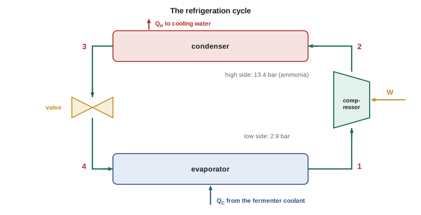
On a pressure-enthalpy diagram (Lesson 9), the cycle is almost a rectangle: two horizontal lines for evaporation and condensation at constant pressure, a vertical line for the expansion valve at constant enthalpy, and a sloped line for compression. The refrigeration effect per kilogram is the enthalpy rise in the evaporator, the compressor work is the enthalpy rise in the compressor, and their ratio is the coefficient of performance.
The expansion valve is the one deliberately irreversible step. Replacing it with an expander would recover some work and raise the COP, but for most refrigerants the work available from expanding a liquid is small and the valve is far cheaper. Large carbon dioxide and natural gas liquefaction plants, where the recoverable work is larger, do use liquid expanders.
Choosing a refrigerant
A good refrigerant has a vapor pressure above atmospheric at the evaporator temperature, so that air cannot leak in, and a moderate pressure at the condenser temperature. It has a large heat of vaporization, so that little fluid needs to circulate. It should be chemically stable, compatible with the equipment, and as safe and environmentally benign as possible. Ammonia scores very well on thermodynamic grounds and has no ozone depletion or direct global warming effect, so it dominates industrial refrigeration in food, beverage and chemical plants. It is toxic and somewhat flammable, which means ammonia plants are built to strict codes with leak detection, ventilation and emergency procedures. Commercial and domestic systems have moved through several generations of synthetic refrigerants as ozone and climate rules have tightened; carbon dioxide itself is increasingly used as a refrigerant in supermarkets and heat pumps.
Worked problem
The fermenter chiller
An ammonia chiller removes 3.0 MW (853 tons of refrigeration) from the fermenter coolant. The evaporator runs at −10 °C (14 °F) and the condenser at 35 °C (95 °F); the compressor's isentropic efficiency is 0.80. Using Peng-Robinson properties, the program finds \(H_1 = \) saturated vapor at −10 °C, \(H_3 = \) saturated liquid at 35 °C, a refrigeration effect of 1107 kJ/kg and an actual compressor work of 286 kJ/kg. Find the COP, the ammonia circulation rate, the compressor power and the condenser duty.
Show solution
- \(COP = 1107/286 = 3.87\).
- \(\dot{m} = 3000/1107 = 2.71\ \text{kg/s}\).
- Compressor power \(= 2.71 \times 286 = 775\ \text{kW}\).
- Condenser duty \(= \dot{Q}_C + \dot{W} = 3000 + 775 = 3775\ \text{kW}\).
Answer: The COP of 3.87 is about two thirds of the Carnot value of 5.85 found in Lesson 7. The gap comes from the irreversible compressor, the throttling valve, and the superheated compressor discharge at about 131 °C, which means heat is rejected over a range of temperatures well above the condensing temperature. The condenser must reject all the heat removed from the fermenters plus the compressor work, so the cooling tower load rises by about 26 percent of the refrigeration duty.
How operating temperatures affect performance
Every kelvin matters in refrigeration. Lowering the evaporator temperature or raising the condenser temperature widens the temperature lift, reduces the COP and raises the compressor power for the same duty. As a rule of thumb, each degree of extra lift costs roughly 2 to 4 percent in power. Designers therefore keep the evaporator as warm as the process allows and the condenser as cool as the cooling medium allows, and they size heat exchangers generously to keep approach temperatures small. In winter, when the condenser can run cooler, the same plant uses noticeably less power.
Worked problem
Condensing the carbon dioxide
Lakeshore Gas condenses 226.5 mol/s (9.97 kg/s, or 79 100 lbm/h) of carbon dioxide from 20 bar and 35 °C to liquid at 20 bar and −20 °C. The ammonia evaporator must run colder, at about −28 °C (−18 °F), to drive heat out of the condensing carbon dioxide, while the ammonia condenser stays at 35 °C. Using the program's Peng-Robinson values, find the condenser duty and the ammonia compressor power.
Show solution
- Carbon dioxide side: \(\dot{Q} = \dot{m}[H(35\ \text{°C}, 20\ \text{bar}, \text{vapor}) - H(-20\ \text{°C}, 20\ \text{bar}, \text{liquid})] = 3380\ \text{kW}\).
- Ammonia cycle at −28 °C / 35 °C with an isentropic efficiency of 0.80: \(COP = 2.37\).
- Compressor power \(= 3380/2.37 = 1425\ \text{kW}\).
Answer: Liquefying the carbon dioxide takes about 1.4 MW of refrigeration power on top of the 2.3 MW of compression power found in Lesson 10, so the whole liquefaction plant needs about 3.7 MW. With about 35.9 t/h of product, that is roughly 100 kWh per metric ton of liquid carbon dioxide. Pre-cooling the gas with cold liquid before it reaches the condenser, or using a two-stage ammonia system, would trim that figure, and the company's designers are evaluating both.
# Vapor-compression refrigeration with ammonia and Linde liquefaction, using Peng-Robinson properties
import math
R = 8.314
def pr_state(T, P, Tc, Pc, w, phase="vap"):
    """Peng-Robinson: returns Z, residual enthalpy H^R (J/mol), residual entropy S^R (J/mol K), ln(fugacity coefficient)."""
    k = 0.37464 + 1.54226 * w - 0.26992 * w ** 2
    sa = 1 + k * (1 - math.sqrt(T / Tc))
    ac = 0.45724 * R ** 2 * Tc ** 2 / Pc
    a, b = ac * sa ** 2, 0.07780 * R * Tc / Pc
    dadT = -ac * k * sa / math.sqrt(T * Tc)
    A, B = a * P / (R * T) ** 2, b * P / (R * T)
    c2, c1, c0 = -(1 - B), A - 3 * B ** 2 - 2 * B, -(A * B - B ** 2 - B ** 3)
    p = c1 - c2 ** 2 / 3; q = 2 * c2 ** 3 / 27 - c2 * c1 / 3 + c0
    disc = (q / 2) ** 2 + (p / 3) ** 3
    if disc > 0:
        u, v = -q / 2 + math.sqrt(disc), -q / 2 - math.sqrt(disc)
        roots = [math.copysign(abs(u) ** (1 / 3), u) + math.copysign(abs(v) ** (1 / 3), v) - c2 / 3]
    else:
        r = math.sqrt(-(p / 3) ** 3); phi = math.acos(max(-1.0, min(1.0, -q / (2 * r)))); m = 2 * math.sqrt(-p / 3)
        roots = [m * math.cos((phi + 2 * math.pi * j) / 3) - c2 / 3 for j in range(3)]
    roots = sorted(z for z in roots if z > B)
    Z = roots[-1] if phase == "vap" else roots[0]
    L = math.log((Z + (1 + math.sqrt(2)) * B) / (Z + (1 - math.sqrt(2)) * B))
    HR = R * T * (Z - 1) + (T * dadT - a) / (2 * math.sqrt(2) * b) * L
    SR = R * math.log(Z - B) + dadT / (2 * math.sqrt(2) * b) * L
    lnphi = Z - 1 - math.log(Z - B) - A / (2 * math.sqrt(2) * B) * L
    return Z, HR, SR, lnphi

# fluid: Tc (K), Pc (Pa), omega, M (g/mol), ideal gas Cp/R constants (A, B, C, D) - approximate values
FL = {"NH3": (405.7, 112.8e5, 0.253, 17.03, (3.578, 3.020e-3, 0.0, -0.186e5)),
      "CO2": (304.2, 73.8e5, 0.224, 44.01, (5.457, 1.045e-3, 0.0, -1.157e5)),
      "N2":  (126.2, 34.0e5, 0.038, 28.01, (3.280, 0.593e-3, 0.0, 0.040e5))}
def H(f, T, P, ph="vap"):
    Tc, Pc, w, M, (A, B, C, D) = FL[f]; T0 = 298.15
    hig = R * (A * (T - T0) + B / 2 * (T ** 2 - T0 ** 2) + C / 3 * (T ** 3 - T0 ** 3) - D * (1 / T - 1 / T0))
    return (hig + pr_state(T, P, Tc, Pc, w, ph)[1]) / M       # kJ/kg
def S(f, T, P, ph="vap"):
    Tc, Pc, w, M, (A, B, C, D) = FL[f]; T0 = 298.15
    sig = R * (A * math.log(T / T0) + B * (T - T0) + C / 2 * (T ** 2 - T0 ** 2) - D / 2 * (1 / T ** 2 - 1 / T0 ** 2) - math.log(P / 1e5))
    return (sig + pr_state(T, P, Tc, Pc, w, ph)[2]) / M       # kJ/(kg K)
def psat(f, T):
    Tc, Pc, w, M, _ = FL[f]; Tr = T / Tc
    P = Pc * math.exp(5.92714 - 6.09648 / Tr - 1.28862 * math.log(Tr) + 0.169347 * Tr ** 6
                      + w * (15.2518 - 15.6875 / Tr - 13.4721 * math.log(Tr) + 0.43577 * Tr ** 6))
    for _ in range(200):
        d = pr_state(T, P, Tc, Pc, w, "liq")[3] - pr_state(T, P, Tc, Pc, w, "vap")[3]
        P *= math.exp(d)
        if abs(d) < 1e-10: break
    return P
def bisect(fun, target, lo, hi):
    for _ in range(80):
        mid = (lo + hi) / 2
        if fun(mid) < target: lo = mid
        else: hi = mid
    return mid

def ammonia_cycle(t_evap, t_cond, eta=0.80):
    Te, Tk = t_evap + 273.15, t_cond + 273.15
    Pe, Pk = psat("NH3", Te), psat("NH3", Tk)
    h1, s1 = H("NH3", Te, Pe), S("NH3", Te, Pe)                  # saturated vapor leaving the evaporator
    T2s = bisect(lambda T: S("NH3", T, Pk), s1, Tk, Tk + 200)
    h2 = h1 + (H("NH3", T2s, Pk) - h1) / eta                     # actual compressor outlet
    T2 = bisect(lambda T: H("NH3", T, Pk), h2, Tk, Tk + 250)
    h3 = H("NH3", Tk, Pk, "liq")                                 # saturated liquid leaving the condenser
    q_evap, w = h1 - h3, h2 - h1                                 # h4 = h3 across the expansion valve
    return Pe, Pk, h1, h2, h3, T2, q_evap, w

Pe, Pk, h1, h2, h3, T2, q, w = ammonia_cycle(-10, 35)
print(f"Ammonia, -10 C / 35 C: Pe = {Pe/1e5:.2f} bar, Pk = {Pk/1e5:.2f} bar, discharge {T2-273.15:.0f} C")
print(f"   refrigeration effect {q:.0f} kJ/kg, compressor work {w:.0f} kJ/kg, COP = {q/w:.2f} (Carnot 5.85)")
load = 3.0e3                                                     # kW of fermenter cooling in summer
m = load / q
print(f"   for {load/1000:.1f} MW of cooling: ammonia {m:.2f} kg/s, compressor power {m*w:.0f} kW, condenser duty {m*(h2-h3):.0f} kW")

# Condensing the carbon dioxide stream: 226.5 mol/s from 20 bar, 35 C vapor to 20 bar, -20 C liquid
m_co2 = 226.5 * 44.01 / 1000                                     # kg/s
q_co2 = m_co2 * (H("CO2", 308.15, 20e5) - H("CO2", 253.15, 20e5, "liq"))
Pe2, Pk2, a1, a2, a3, T22, q2, w2 = ammonia_cycle(-28, 35)
print(f"CO2 condenser duty {q_co2:.0f} kW; ammonia at -28 C / 35 C: COP {q2/w2:.2f}, compressor power {q_co2 * w2 / q2:.0f} kW")

# Linde liquefaction of nitrogen: feed 200 bar and 300 K, vapor leaves the exchanger at 1 bar and 295 K
Tsat = bisect(lambda T: psat("N2", T), 1.013e5, 60, 120)
h_hp, h_vap_out = H("N2", 300, 200e5), H("N2", 295, 1.013e5)
h_liq = H("N2", Tsat, 1.013e5, "liq")
y = (h_vap_out - h_hp) / (h_vap_out - h_liq)
print(f"Nitrogen normal boiling point by Peng-Robinson: {Tsat:.1f} K")
print(f"Linde process from 200 bar and 300 K: fraction liquefied y = {y:.3f}")Ammonia, -10 C / 35 C: Pe = 2.88 bar, Pk = 13.41 bar, discharge 131 C refrigeration effect 1107 kJ/kg, compressor work 286 kJ/kg, COP = 3.87 (Carnot 5.85) for 3.0 MW of cooling: ammonia 2.71 kg/s, compressor power 775 kW, condenser duty 3775 kW CO2 condenser duty 3380 kW; ammonia at -28 C / 35 C: COP 2.37, compressor power 1425 kW Nitrogen normal boiling point by Peng-Robinson: 77.3 K Linde process from 200 bar and 300 K: fraction liquefied y = 0.072
The program builds every state from the Peng-Robinson equation: vapor pressures by equal fugacities, enthalpies and entropies from the ideal gas state plus residuals, the isentropic compressor outlet by bisection on entropy, and the actual outlet from the efficiency. It is a compact version of what a property package does inside a process simulator.
Liquefying gases: the Linde process
Gases such as nitrogen, oxygen and natural gas have critical temperatures far below ambient, so no ordinary refrigerant can condense them. Liquefaction instead uses the Joule-Thomson effect of Lesson 8. In the Linde process, gas compressed to high pressure and cooled to ambient temperature passes through a counter-current heat exchanger and then through a throttle valve. Throttling cools it, and the cold, low-pressure gas that does not liquefy flows back through the heat exchanger, precooling the incoming high-pressure gas. Each pass gets colder, until part of the gas condenses after the valve. At steady state, an energy balance around the exchanger, valve and separator gives the fraction liquefied.
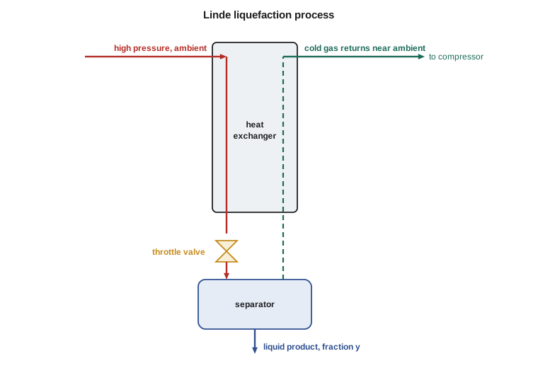
For liquefaction to work, the high-pressure feed must have a lower enthalpy than the low-pressure vapor at the same temperature, which is exactly the condition of a positive Joule-Thomson effect, a negative residual enthalpy at high pressure. Hydrogen and helium have negative Joule-Thomson coefficients at room temperature and must be precooled, with liquid nitrogen for hydrogen, before a Linde stage can liquefy them. The Claude process improves on Linde by sending part of the high-pressure gas through an expander, which cools it much more than a throttle valve and recovers work.
Worked problem
Liquid nitrogen by the Linde process
Nitrogen is compressed to 200 bar (2900 psia) and cooled to 300 K (80 °F). Unliquefied vapor leaves the warm end of the heat exchanger at 1 atm and 295 K (71 °F). Using Peng-Robinson enthalpies, find the fraction liquefied.
Show solution
- The program finds the normal boiling point of nitrogen as 77.3 K by equating fugacities at 1 atm, and takes the liquid product as saturated liquid there.
- \(y = [H(295\ \text{K}, 1\ \text{atm}) - H(300\ \text{K}, 200\ \text{bar})]/[H(295\ \text{K}, 1\ \text{atm}) - H^l(77.3\ \text{K}, 1\ \text{atm})] = 0.072\).
Answer: Only about 7 percent of the gas liquefies per pass, and the rest must be recompressed. That is why the simple Linde cycle is energy-intensive and why industrial air separation plants use expanders, precooling and heat integration. Kingfisher buys its liquid nitrogen for purging rather than making it, but the same principles explain the carbon dioxide liquefier's design.
Pulling the course together
The three Kingfisher projects show how the parts of this course fit together. Lakeshore Gas's liquefaction unit needed phase diagrams (Lesson 2), equations of state for gas and liquid (Lessons 3 to 5), residual properties (Lesson 8), diagrams and tables (Lesson 9), compressor calculations (Lesson 10) and refrigeration (this lesson). The steam turbine study needed the second law (Lesson 7), steam tables and the Rankine cycle (Lessons 9 to 11). The fermenter chiller needed heat effects (Lesson 6) and refrigeration cycles. In every case, the first law gave the energy, the second law gave the limit, and property methods supplied the numbers. Thermodynamics II takes the same tools into mixtures, phase equilibrium and chemical reaction equilibrium.
Common mistakes
MistakeForgetting that the condenser rejects the refrigeration duty plus the compressor work.
InsteadQ_H = Q_C + W; size the condenser and cooling tower for the sum.
MistakeTreating the expansion valve as isentropic.
InsteadThrottling is isenthalpic: H4 = H3.
MistakeUsing the Carnot COP to size a compressor.
InsteadReal COPs are typically 60 to 75 percent of Carnot; use real cycle calculations.
MistakeExpecting a Linde stage to liquefy hydrogen from room temperature.
InsteadHydrogen warms on throttling at room temperature; precool it below its inversion temperature first.
MistakeIgnoring the temperature lift.
InsteadEach extra kelvin of lift costs a few percent in power; keep evaporators warm and condensers cool.
Summary and key terms
- Vapor compression: evaporate, compress, condense and throttle; COP = (H1 − H4)/(H2 − H1).
- On a P-h diagram the cycle is nearly a rectangle; the valve is a vertical line at constant enthalpy.
- Ammonia is the dominant industrial refrigerant: efficient and climate-neutral, but toxic.
- The condenser rejects Q_C + W; larger temperature lifts lower the COP.
- Linde liquefaction uses the Joule-Thomson effect with counter-current precooling; y = (H_vap,out − H_feed)/(H_vap,out − H_liq).
- Expanders (Claude process) liquefy gases more efficiently than throttle valves.
- Refrigerant
- The working fluid of a refrigeration cycle.
- Refrigeration effect
- Heat absorbed per kilogram of refrigerant in the evaporator.
- Expansion valve
- The throttle that drops refrigerant pressure at constant enthalpy.
- Temperature lift
- The difference between condensing and evaporating temperatures.
- Linde process
- A gas liquefaction process using throttling and counter-current heat exchange.
- Inversion temperature
- The temperature above which a gas warms rather than cools on throttling.
- Ton of refrigeration
- A unit of refrigeration duty equal to 12 000 Btu/h, about 3.517 kW.
Practice problems
Work each problem on paper first, then reveal the answer to check.
A cycle has H1 = 1450, H2 = 1700 and H3 = H4 = 370 kJ/kg. Find the COP.
Show answer
(1450 − 370)/(1700 − 1450) = 4.32.
Using the program, what is the ammonia compressor discharge temperature for the −10 °C / 35 °C cycle?
Show answer
About 131 °C.
A chiller removes 500 kW with a COP of 4. Find the compressor power and condenser duty.
Show answer
125 kW and 625 kW.
Convert 3.0 MW of refrigeration to tons.
Show answer
3000/3.517 = 853 tons.
Why does the carbon dioxide condenser need a colder ammonia evaporator than the fermenter chiller?
Show answer
The carbon dioxide condenses at −20 °C, so the ammonia must evaporate below that to drive heat across the exchanger.
In the Linde nitrogen example, what happens to the 93 percent of gas that does not liquefy?
Show answer
It returns through the heat exchanger to precool the feed and goes back to the compressor.
Lesson quiz · 5 questions
Score 60% or more to complete this lesson.
Create a free account to save your progress, take quizzes and earn a certificate.