
CHE-220 · Lesson 10 of 12 · 27 min
Flow processes: nozzles, throttling, compressors and turbines
Most of the equipment that moves energy in a chemical plant is steady-flow equipment: valves that drop pressure, nozzles that turn enthalpy into velocity, compressors and pumps that raise pressure, and turbines and expanders that extract work. With real-gas properties from Lessons 4 to 9 and the energy and entropy balances from Lessons 1 and 7, Theo can now do what the compressor vendor did: work out how many stages the Lakeshore Gas compressor needs, how hot the gas gets, and how much power the motors must supply. The same tools give the work from Kingfisher's proposed steam turbine and the cooling produced when dense carbon dioxide is throttled.
The two balances for steady-flow devices
Every device in this lesson is analyzed with the steady-flow energy balance and the steady-flow entropy balance, for a single stream in and out. The energy balance gives the work or heat. The entropy balance, with zero entropy generation, gives the best possible performance; the real device is then described by an efficiency that compares it with that ideal.
Nozzles and diffusers
A nozzle is a shaped passage that accelerates a fluid by lowering its pressure. It is adiabatic and does no shaft work, so the enthalpy drop appears entirely as kinetic energy. Starting from a negligible inlet velocity, the exit velocity follows from the enthalpy change alone. A diffuser does the reverse, slowing a fluid to raise its pressure. Turbines use nozzles to create high-velocity jets of steam that drive the blades; ejectors use them to create suction for vacuum systems, such as the vacuum that Kingfisher's evaporators run under.
An enthalpy drop of only 100 kJ/kg gives an exit velocity of about 447 m/s, faster than the speed of sound in air. That illustrates how much energy kinetic terms represent when they are large. Gas flow through a converging nozzle reaches the local speed of sound at the throat when the pressure ratio falls below a critical value, about 0.53 for air and 0.55 for steam, and further lowering the downstream pressure does not increase the flow. That choked-flow limit sets the capacity of relief valves and flow restrictors, and fluid mechanics courses treat it in detail.
Throttling
A throttling device is a valve, orifice or porous plug that drops pressure with no shaft work, negligible heat transfer and negligible change in kinetic energy. The energy balance reduces to constant enthalpy. For an ideal gas, constant enthalpy means constant temperature, so throttling has no thermal effect. For a real gas, the Joule-Thomson coefficient of Lesson 8 sets the temperature change, and for liquids near saturation, throttling produces a flash, as Lesson 9 showed.
Throttling is always irreversible: entropy rises, and the pressure drop that could have driven an expander or turbine is wasted. That waste is accepted in control valves because they are cheap and reliable. In large refrigeration and liquefaction plants, the expansion valve is sometimes replaced by an expander that recovers part of the work, which Lesson 12 discusses.
Worked problem
Throttling dense carbon dioxide
In the pipeline option, carbon dioxide at 60 bar (870 psia) and 40 °C (104 °F) is let down to 20 bar (290 psia) through a control valve at the customer's site. Using Peng-Robinson enthalpies, find the outlet temperature.
Show solution
- Constant enthalpy: find \(T_2\) such that \(H(T_2, 20\ \text{bar}) = H(313.15\ \text{K}, 60\ \text{bar})\), with \(H = H^{ig} + H^R\).
- Bisection on \(T_2\) in the program converges to \(T_2 = 261.9\ \text{K}\), or −11.3 °C.
- The vapor pressure at −11 °C is about 25 bar, so the outlet at 20 bar is still vapor, but only a few degrees from condensing.
Answer: The gas cools by about 51 K (92 °F), an average of about 1.3 K per bar, because near the critical point carbon dioxide's Joule-Thomson coefficient is large. Pipeline letdown stations for carbon dioxide therefore need heating upstream of the valve, or materials rated for low temperature downstream, to avoid brittle steel and dry ice formation if the pressure ever falls further.
Turbines and expanders
A turbine extracts shaft work from a high-pressure fluid. It is nearly adiabatic, and changes in kinetic and potential energy across the whole machine are small, so the work equals the enthalpy drop. The best possible turbine is reversible and adiabatic, which means isentropic: its outlet state has the same entropy as its inlet. A real turbine produces less work than the isentropic one, and its isentropic efficiency is the ratio of actual work to isentropic work for the same inlet state and outlet pressure.
Worked problem
Work from a back-pressure steam turbine
Kingfisher's study turbine takes steam at 4.0 MPa (580 psia) and 400 °C (752 °F) (\(H_1 = 3213.6\ \text{kJ/kg}\), \(S_1 = 6.7690\ \text{kJ/(kg·K)}\)) and exhausts at 0.4 MPa (58 psia), the pressure of the existing process steam header. At 0.4 MPa, saturated values are \(H^l = 604.74\), \(\Delta H^{lv} = 2133.8\ \text{kJ/kg}\), \(S^l = 1.7766\) and \(\Delta S^{lv} = 5.1193\ \text{kJ/(kg·K)}\) (approximate table values). With an isentropic efficiency of 0.80, find the work per kilogram and the exhaust state.
Show solution
- Isentropic outlet: \(x_S = (6.7690 - 1.7766)/5.1193 = 0.9752\); \(H_{2,S} = 604.74 + 0.9752 \times 2133.8 = 2685.6\ \text{kJ/kg}\).
- Isentropic work: \(3213.6 - 2685.6 = 528.0\ \text{kJ/kg}\). Actual work: \(0.80 \times 528.0 = 422.4\ \text{kJ/kg}\).
- Actual outlet enthalpy: \(H_2 = 3213.6 - 422.4 = 2791.2\ \text{kJ/kg}\), above the saturated vapor value of 2738.6 kJ/kg, so the exhaust is slightly superheated, at about 168 °C by interpolation in the superheated table.
Answer: Every kilogram of steam passed through the turbine yields 422 kJ of work, and the exhaust is still useful heating steam. Irreversibility is not entirely wasted here: the 106 kJ/kg the turbine fails to extract stays in the exhaust as extra superheat, which the reboilers can still use. Lesson 11 builds the full combined heat and power case on this example.
Compressors and pumps
Compressors raise gas pressure; pumps do the same for liquids. Both need work, and both are compared with an isentropic machine. The isentropic efficiency of a compressor is the ratio of isentropic work to actual work, the reverse of the turbine definition, so that it stays below 1. Typical isentropic efficiencies are 0.70 to 0.85 for centrifugal and reciprocating compressors and 0.60 to 0.85 for centrifugal pumps. Because liquids are nearly incompressible, the isentropic pump work is simply \(V\,\Delta P\).
Multistage compression with intercooling
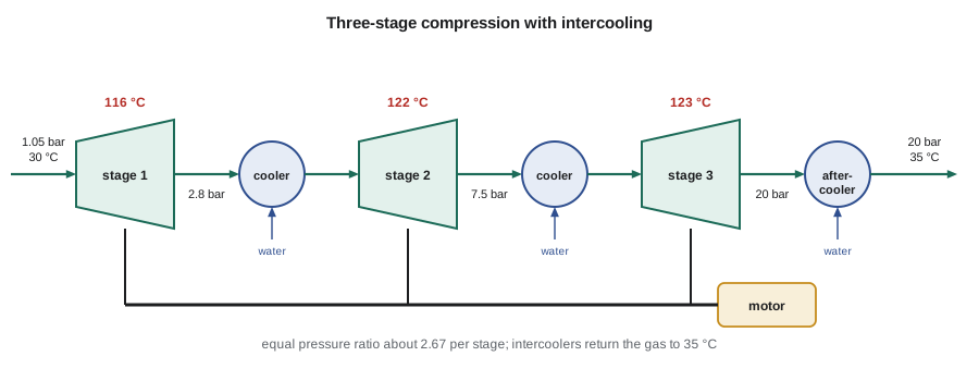
Compressing carbon dioxide from 1 bar to 20 bar in one stage would need a large amount of work and would heat the gas above 300 °C, too hot for seals, lubricants and the gas's later processing. Splitting the compression into stages with intercoolers between them brings the gas back to near cooling-water temperature before each stage. Because hot gas has a larger volume, and the work integral \(\int V\,dP\) is larger for larger volumes, intercooling reduces the total work. For ideal gases with equal inlet temperatures, the total work is smallest when every stage has the same pressure ratio, \(r = (P_{out}/P_{in})^{1/N}\).
Worked problem
Sizing the carbon dioxide compressor
Carbon dioxide at 226.5 mol/s (1797 lbmol/h) is compressed from 1.05 bar (15.2 psia) and 30 °C (86 °F) to 20 bar (290 psia). Each stage has an isentropic efficiency of 0.80, and intercoolers return the gas to 35 °C (95 °F). Using Peng-Robinson properties, compare one, two and three stages with equal pressure ratios.
Show solution
- For each stage, find the isentropic outlet temperature by solving \(S(T_{2S}, P_2) = S(T_1, P_1)\), then \((\Delta H)_S = H(T_{2S}, P_2) - H(T_1, P_1)\).
- Actual work \(\Delta H = (\Delta H)_S/0.80\); find the actual outlet temperature by solving \(H(T_2, P_2) = H(T_1, P_1) + \Delta H\).
- The program gives 2.85 MW (3820 hp) with one stage (outlet about 321 °C), 2.44 MW (3270 hp) with two stages (outlets about 162 and 170 °C) and 2.32 MW (3110 hp) with three stages (outlets about 116 to 123 °C).
Answer: Going from one stage to three saves about 0.5 MW, roughly 4 GWh a year at continuous operation, and keeps every outlet below about 125 °C. A fourth stage would save a little more power but add another cooler and casing, so most carbon dioxide compressors of this size use three or four stages. The three-stage work of 10.2 kJ/mol is about 1.4 times the reversible minimum of 7.2 kJ/mol found in Lesson 8, a typical ratio for real compressor trains.
# Compressor train, throttling and turbine calculations with real-gas (Peng-Robinson) properties
import math
R = 8.314
def pr_state(T, P, Tc, Pc, w, phase="vap"):
    """Peng-Robinson: returns Z, residual enthalpy H^R (J/mol), residual entropy S^R (J/mol K), ln(fugacity coefficient)."""
    k = 0.37464 + 1.54226 * w - 0.26992 * w ** 2
    sa = 1 + k * (1 - math.sqrt(T / Tc))
    ac = 0.45724 * R ** 2 * Tc ** 2 / Pc
    a, b = ac * sa ** 2, 0.07780 * R * Tc / Pc
    dadT = -ac * k * sa / math.sqrt(T * Tc)
    A, B = a * P / (R * T) ** 2, b * P / (R * T)
    c2, c1, c0 = -(1 - B), A - 3 * B ** 2 - 2 * B, -(A * B - B ** 2 - B ** 3)
    p = c1 - c2 ** 2 / 3; q = 2 * c2 ** 3 / 27 - c2 * c1 / 3 + c0
    disc = (q / 2) ** 2 + (p / 3) ** 3
    if disc > 0:
        u, v = -q / 2 + math.sqrt(disc), -q / 2 - math.sqrt(disc)
        roots = [math.copysign(abs(u) ** (1 / 3), u) + math.copysign(abs(v) ** (1 / 3), v) - c2 / 3]
    else:
        r = math.sqrt(-(p / 3) ** 3); phi = math.acos(max(-1.0, min(1.0, -q / (2 * r)))); m = 2 * math.sqrt(-p / 3)
        roots = [m * math.cos((phi + 2 * math.pi * j) / 3) - c2 / 3 for j in range(3)]
    roots = sorted(z for z in roots if z > B)
    Z = roots[-1] if phase == "vap" else roots[0]
    L = math.log((Z + (1 + math.sqrt(2)) * B) / (Z + (1 - math.sqrt(2)) * B))
    HR = R * T * (Z - 1) + (T * dadT - a) / (2 * math.sqrt(2) * b) * L
    SR = R * math.log(Z - B) + dadT / (2 * math.sqrt(2) * b) * L
    lnphi = Z - 1 - math.log(Z - B) - A / (2 * math.sqrt(2) * B) * L
    return Z, HR, SR, lnphi

Tc, Pc, w = 304.2, 73.8e5, 0.224                     # carbon dioxide (approximate)
A_, B_, D_ = 5.457, 1.045e-3, -1.157e5
def H(T, P):
    hig = R * (A_ * (T - 298.15) + B_ / 2 * (T ** 2 - 298.15 ** 2) - D_ * (1 / T - 1 / 298.15))
    return hig + pr_state(T, P, Tc, Pc, w)[1]
def S(T, P):
    sig = R * (A_ * math.log(T / 298.15) + B_ * (T - 298.15) - D_ / 2 * (1 / T ** 2 - 1 / 298.15 ** 2) - math.log(P / 1e5))
    return sig + pr_state(T, P, Tc, Pc, w)[2]
def solve_T(f, target, lo=200.0, hi=700.0):
    for _ in range(80):
        mid = (lo + hi) / 2
        if f(mid) < target: lo = mid
        else: hi = mid
    return mid

n = 226.5                                            # mol/s of carbon dioxide
eta = 0.80                                           # isentropic efficiency of each stage
def train(stages, P_in=1.05e5, P_out=20e5, T_suction=303.15, T_cool=308.15):
    r = (P_out / P_in) ** (1 / stages); P1, T1, W, rows = P_in, T_suction, 0.0, []
    for k in range(stages):
        P2 = P1 * r
        T2s = solve_T(lambda T: S(T, P2), S(T1, P1))
        dHs = H(T2s, P2) - H(T1, P1)
        dH = dHs / eta
        T2 = solve_T(lambda T: H(T, P2), H(T1, P1) + dH)
        rows.append((P1 / 1e5, P2 / 1e5, T2 - 273.15, dH * n / 1e6)); W += dH
        P1, T1 = P2, T_cool                          # intercooled to 35 C before the next stage
    return W, rows
for stages in (1, 2, 3):
    W, rows = train(stages)
    detail = "; ".join(f"{a:.2f}->{b:.2f} bar, out {t:.0f} C, {p:.2f} MW" for a, b, t, p in rows)
    print(f"{stages} stage(s): total {W * n / 1e6:.2f} MW ({W/1000:.2f} kJ/mol)  [{detail}]")

# Throttling dense carbon dioxide gas from 60 bar and 40 C to 20 bar (constant enthalpy)
h_in = H(313.15, 60e5)
T_out = solve_T(lambda T: H(T, 20e5), h_in)
print(f"Throttling 60 bar, 40 C to 20 bar: outlet {T_out - 273.15:.1f} C (an ideal gas would stay at 40 C)")

# Steam turbine: 4 MPa, 400 C to 0.4 MPa, isentropic efficiency 0.80 (approximate steam-table values)
h1, s1 = 3213.6, 6.7690
hf, hfg, sf, sfg = 604.74, 2133.8, 1.7766, 5.1193     # saturated at 0.4 MPa
x_s = (s1 - sf) / sfg; h2s = hf + x_s * hfg
h2 = h1 - 0.80 * (h1 - h2s)
print(f"Turbine: isentropic outlet x = {x_s:.4f}, h2s = {h2s:.1f} kJ/kg; actual h2 = {h2:.1f} kJ/kg, work {h1 - h2:.1f} kJ/kg")

# Nozzle: exit velocity from an enthalpy drop, starting from rest
for dh in (10, 50, 100):
print(f"Nozzle enthalpy drop {dh:3d} kJ/kg -> exit velocity {math.sqrt(2 * dh * 1000):.0f} m/s")1 stage(s): total 2.85 MW (12.59 kJ/mol) [1.05->20.00 bar, out 321 C, 2.85 MW] 2 stage(s): total 2.44 MW (10.79 kJ/mol) [1.05->4.58 bar, out 162 C, 1.22 MW; 4.58->20.00 bar, out 170 C, 1.22 MW] 3 stage(s): total 2.32 MW (10.23 kJ/mol) [1.05->2.80 bar, out 116 C, 0.78 MW; 2.80->7.49 bar, out 122 C, 0.78 MW; 7.49->20.00 bar, out 123 C, 0.76 MW] Throttling 60 bar, 40 C to 20 bar: outlet -11.3 C (an ideal gas would stay at 40 C) Turbine: isentropic outlet x = 0.9752, h2s = 2685.6 kJ/kg; actual h2 = 2791.2 kJ/kg, work 422.4 kJ/kg Nozzle enthalpy drop 10 kJ/kg -> exit velocity 141 m/s Nozzle enthalpy drop 50 kJ/kg -> exit velocity 316 m/s Nozzle enthalpy drop 100 kJ/kg -> exit velocity 447 m/s
The program applies the real-gas methods of Lesson 8 throughout: entropy and enthalpy from the ideal gas state plus Peng-Robinson residuals, with bisection to find outlet temperatures. The same approach, with a reference equation in place of Peng-Robinson, is what compressor vendors and process simulators use.
Common mistakes
MistakeUsing the actual outlet temperature to find the isentropic work.
InsteadFind the isentropic outlet from S2 = S1 first; the actual outlet comes from the efficiency.
MistakeDefining compressor efficiency as actual work over isentropic work.
InsteadCompressor efficiency is isentropic work over actual work, so it stays below 1.
MistakeAssuming throttling never changes temperature.
InsteadThat holds only for ideal gases; real gases and flashing liquids change temperature.
MistakeIgnoring kinetic energy in nozzles.
InsteadIn nozzles, the enthalpy drop becomes kinetic energy; it is the whole point of the device.
MistakeChoosing unequal stage pressure ratios by habit.
InsteadEqual ratios minimize total work for equal intercooled inlet temperatures.
Summary and key terms
- Steady-flow devices use the energy balance for work or heat and the entropy balance for ideal limits.
- Nozzles: u2 = √(2(H1 − H2)); flow chokes at a critical pressure ratio.
- Throttling is isenthalpic and irreversible; real gases cool by the Joule-Thomson effect.
- Turbines: η = actual work/isentropic work; compressors: η = isentropic work/actual work.
- Pump work ≈ VΔP/η because liquids are nearly incompressible.
- Multistage compression with intercooling and equal pressure ratios reduces work and outlet temperatures.
- Nozzle
- A passage that converts enthalpy into kinetic energy by lowering pressure.
- Throttling
- An adiabatic pressure drop with no work, at constant enthalpy.
- Isentropic efficiency
- The ratio comparing a real turbine or compressor with an isentropic one between the same pressures.
- Intercooler
- A heat exchanger that cools gas between compression stages.
- Choked flow
- The maximum flow through a nozzle, reached when the throat velocity equals the speed of sound.
- Expander
- A turbine that recovers work from a gas or two-phase stream instead of throttling it.
Practice problems
Work each problem on paper first, then reveal the answer to check.
Steam enters a nozzle at negligible velocity and leaves after an enthalpy drop of 60 kJ/kg. Find the exit velocity.
Show answer
√(2 × 60 000) = 346 m/s.
A turbine has isentropic work 500 kJ/kg and isentropic efficiency 0.85. Find the actual work.
Show answer
425 kJ/kg.
Find the equal stage pressure ratio for compression from 1 to 64 bar in three stages.
Show answer
64^(1/3) = 4.0.
Using the program, what is the outlet temperature of a single stage compressing carbon dioxide from 1.05 to 20 bar?
Show answer
About 321 °C.
A pump raises 20 kg/s of water by 15 bar with an efficiency of 0.70. Find the power.
Show answer
0.001 × 1.5×10⁶ × 20/0.70 = 42.9 kW.
Why is throttling always irreversible?
Show answer
It drops pressure with no work recovered, generating entropy at constant enthalpy.
Lesson quiz · 5 questions
Score 60% or more to complete this lesson.
Create a free account to save your progress, take quizzes and earn a certificate.